Drying system based on heat pipe and use method of drying system

A technology of drying system and hot air system, which is applied in the fields of compounding, coating and printing, and can solve the problems of affecting production cost, large energy consumption of drying system, and high operating cost

Inactive Publication Date: 2013-09-04
SHAANXI BEIREN PRINTING MACHINERY
View PDF4 Cites 7 Cited by
  • Summary
  • Abstract
  • Description
  • Claims
  • Application Information

AI Technical Summary

Problems solved by technology

Regardless of the printing machine, compound machine, or coating machine, the drying system consumes a lot of energy, and the operating cost of the system is high, which seriously affects the production cost.

Method used


Image

  • Drying system based on heat pipe and use method of drying system

Examples


Embodiment Construction

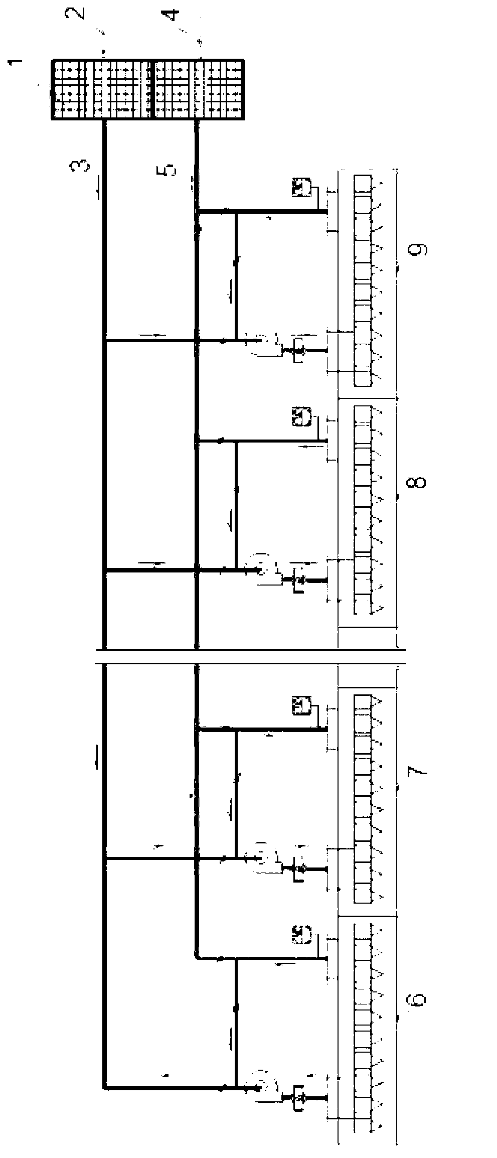
[0014] The present invention is described in further detail below in conjunction with accompanying drawing:

[0015] see figure 1 , when the drying system of the present invention is in operation, fresh hot air enters the drying equipment and is discharged through the exhaust pipe. The exhaust pipe is equipped with a secondary return air device, and a part of the air is directly used in the secondary heat cycle, and the other part is used as a safety exhaust. The amount is exhausted out of the system. As part of the safe air exhaust, a heat pipe heat exchanger is used to efficiently recycle the remaining heat and preheat the fresh air entering the system. The working principle of the heat pipe heat exchanger: the exhaust air passes through the evaporation end of the heat pipe heat exchanger, one end of the heat pipe is heated, the medium liquid in the capillary evaporates rapidly, and the steam flows to the other end (condenser end) under a small pressure difference, and the ...


PUM


Abstract

The invention discloses a drying system based on a heat pipe. The drying system based on the heat pipe comprises a hot-air system and the heat pipe, wherein the hot-air system and the heat pipe are arranged in parallel. The heat pipe comprises a heating section and a cooling section. An air inlet pipe of the hot-air system penetrates through the heating section. An exhaust pipe of the hot-air system penetrates through the cooling section. According to a use method of the drying system, the hot-air system and the heat pipe are arranged in parallel, the heat pipe comprises the heating section and the cooling section, the air inlet pipe of the hot-air system penetrates through the heating section, and the exhaust pipe of the hot-air system penetrates through the cooling section. The drying system based on the heat pipe has the advantages that a heat recovery device of the drying system is utilized in devices such as a printing machine, a compound machine and a coating machine for absorbing and utilizing more than 60 percent of exhaust air heat energy, 30 percent of hot air in a circulation system is directly recycled, 60 percent of the remaining 70 percent of the exhaust air heat energy is recycled, therefore, a heat recovery utilization rate of the whole system can reach more than 70 percent, and insufficient partial energy is supplemented by an electric heating device arranged in the drying system.

Description

technical field [0001] The invention belongs to the fields of printing, coating and compounding, and relates to a method for utilizing heat energy, in particular to a drying system based on a heat pipe and its application method. Background technique [0002] Our country has a large population and poor resources, and energy has restricted the development of our country's economy to some extent. Regardless of the printing machine, compound machine, or coating machine, the drying system consumes a lot of energy, and the operating cost of the system is high, which seriously affects the production cost. [0003] With the international community's requirements for environmental protection, energy saving and consumption reduction, choosing green energy and finding renewable energy has always been the common goal of society and enterprises. [0004] Heat pipe (heat pipe) technology was widely used in aerospace, military and other industries before. Since it was introduced into the...

Claims


Application Information

Patent Timeline
IPC IPC(8): F26B21/00
CPCY02P70/10
Inventor 薛志成李彦锋李征张廷群彭安信
Owner SHAANXI BEIREN PRINTING MACHINERY
Why Eureka
Try Eureka