An ultrasonic pipe wall thickness measuring device

An ultrasonic wave and tube wall technology, applied in the field of ultrasonic waves, can solve problems such as ultrasonic wave velocity scattering, detection sensitivity drop, and speed instability, and achieve the effects of reducing rotational resistance, increasing surface cleanliness, and compact device structure

Active Publication Date: 2015-12-23
南通赛科检测装备技术有限公司
View PDF4 Cites 2 Cited by
  • Summary
  • Abstract
  • Description
  • Claims
  • Application Information

AI Technical Summary

Problems solved by technology

This kind of test device has such defects: the rotation speed of the reflector is affected by the water flow, causing the speed to be unstable; at the same time, because the water flow is used as the driving force for the turbine to rotate, the axially flowing water collides with the surface of the reflector, which will cause turbulence and tiny bubbles , so that the ultrasonic wave velocity is seriously scattered, causing noise to increase and detection sensitivity to decrease. This structural device is only suitable for testing small-diameter pipes such as heat exchangers and condensers with a diameter of less than 10 cm. In addition, the use of hydraulic power as turbine power determines this device. Can only be tested when moving in one direction

Method used


Image

  • An ultrasonic pipe wall thickness measuring device
  • An ultrasonic pipe wall thickness measuring device
  • An ultrasonic pipe wall thickness measuring device

Examples


Embodiment Construction

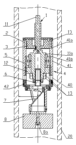
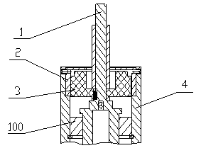
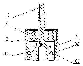
[0025] control figure 1 , the ultrasonic tube wall thickness measuring device of the present invention is placed in the pipeline to be tested, and is mainly composed of an ultrasonic probe 6, a mirror 7, a fixed shaft 1, a stator 3, a rotor 2 and a rotor housing 4, and the fixed shaft 1 is placed inside the rotor housing. At the center, the stator 3 is concentrically connected to the fixed shaft, the rotor 2 is concentrically connected to the inner wall of the rotor housing 4, the ultrasonic probe 6 is connected to the fixed shaft 1, and the mirror 7 is connected to the rotor housing 4, and is arranged such that The reflection mirror surface forms an acute angle with the propagation direction of the ultrasonic wave.

[0026] In the above solution, the rotor 2 is a magnetic steel connected to the inner wall of the rotor casing, and the stator 3 is a coil winding. In order to make the reflection of the ultrasonic wave emitted by the ultrasonic probe 6 by the reflective mirror ...


PUM


Abstract

The invention relates to an ultrasonic pipe wall thickness measuring device. The ultrasonic pipe wall thickness measuring device comprises an ultrasonic probe, a reflector, a fixed shaft, a stator, a rotor and a rotor outer shell. The fixed shaft is arranged in the center inside the rotor outer shell, the stator is connected to the fixed shaft in a concentric mode, the rotor is connected to the inner side wall of the rotor outer shell in a concentric mode, the ultrasonic probe is connected to the fixed shaft, the reflector is connected to the rotor outer shell, and an acute angle is formed between the direction of a reflector face and the direction of ultrasonic propagation. According to the ultrasonic pipe wall thickness measuring device, the stator is connected to the fixed shaft, the fixed shaft does not rotate, the rotor is arranged on the rotor outer shell and rotates around the fixed shaft, the rotor rotates evenly and stably after being powered on and drives the reflector to rotate, and ultrasonic waves generated by the probe are vertically reflected to the inner circumferential surface of a pipe wall through the reflector; when the ultrasonic pipe wall thickness measuring device is used underwater, water in the device is centrifugally thrown out through holes formed in the circumferential direction, impact of axial water flow on the reflector face is quickened, the reflector face can be cleaned automatically, therefore, the degree of finish of the reflector face is improved, the ultrasonic waves can not be scattered, and consequently, detection precision is improved.

Description

technical field [0001] The invention relates to ultrasonic technology, in particular to an ultrasonic tube wall thickness measuring device. Background technique [0002] At present, the test device for measuring the thickness of the pipe wall by ultrasonic waves is basically as follows: Figure 5 structure shown. Distribute multiple probes along the circumferential direction, each probe corresponds to a certain area of ​​the pipe wall, so as to detect the thickness of the entire pipe wall, and the detection coverage depends on the number of probes distributed in the circumferential direction. Such a detection structure requires multiple probes, and therefore requires a multi-channel detection instrument, which not only increases the volume of the equipment, but also increases the manufacturing cost. [0003] At present, there is also an ultrasonic testing device for detecting the thickness of the underwater pipe wall, which uses hydraulic power as the power of the turbine r...

Claims


Application Information

Patent Timeline
Patent Type & Authority Patents(China)
IPC IPC(8): G01B17/02
Inventor 朱汉俊郑凯沈鸿飞刘海鹏郭振祥
Owner 南通赛科检测装备技术有限公司
Why Eureka
Try Eureka