Method and device for measuring cable force

A measurement method and tension technology, applied in the field of cable force measurement methods and devices, can solve the problems of large measurement results, complex signal processing, and small application range, and achieve the effects of easy portability and installation, high measurement accuracy, and wide application range.

Active Publication Date: 2015-10-28
SOUTH CHINA UNIV OF TECH
View PDF5 Cites 0 Cited by
  • Summary
  • Abstract
  • Description
  • Claims
  • Application Information

AI Technical Summary

Problems solved by technology

[0005] Disadvantages: 1. The cost is too high; 2. It can only measure the tension of the cable head; 3. The durability of the sensor has not been verified in the actual project; 4. The scope of application is small, and it must be installed on the anchorage and the cable hole pad Between the boards, it is inconvenient to install the cable-stayed bridge that has been built; 5. Due to the large size of the pressure sensor, it will have a great impact on the appearance of the building
At the same time, it is difficult to automatically calculate the nth order natural frequency of the steel cable or the frequency difference Δf between two adjacent orders by using the spectrogram
Therefore, the result of measuring the cable force by the frequency method is related to various factors such as the installation position of the vibration pickup, whether the cable is vibrating, the span, sag, slope and boundary conditions of the tested cable, and the signal processing is relatively complicated. 24 / 7 monitoring is not possible
[0009] 2. When the vibration frequencies of the adjacent two orders of the structure are very similar, it will be very difficult to use the frequency vibration method to measure the cable force
Therefore, the frequency vibration method is only suitable for simple cable system (single cable) structures, and for complex cable system (cable group) structures, there is a large error in the measurement results
[0010] 3. The frequency vibration method is only applicable to the measurement of the force of the cable after the tensioning is completed, and it will not be possible to measure the force of the cable during the tensioning process.
Therefore, cable force measurements during passive cable construction will not be able to measure

Method used


Image

  • Method and device for measuring cable force
  • Method and device for measuring cable force
  • Method and device for measuring cable force

Examples


Embodiment 1

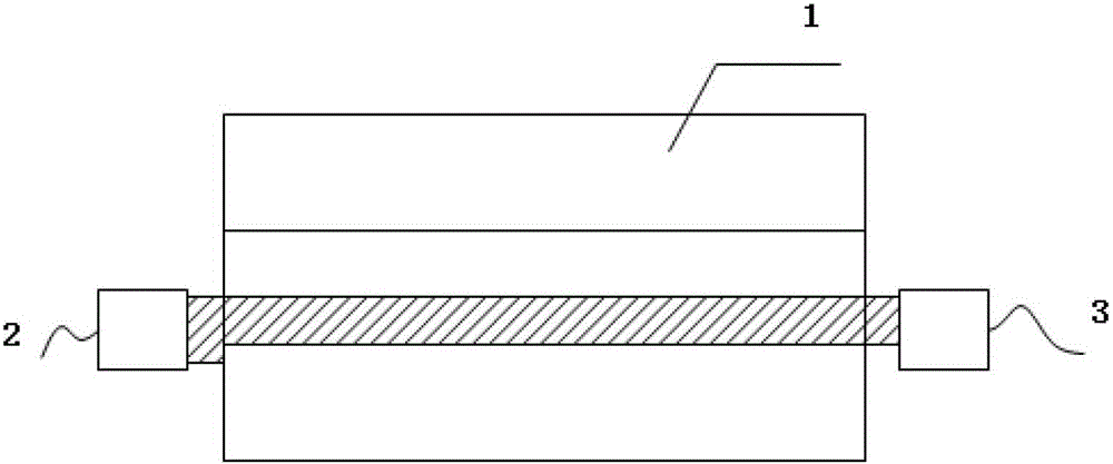
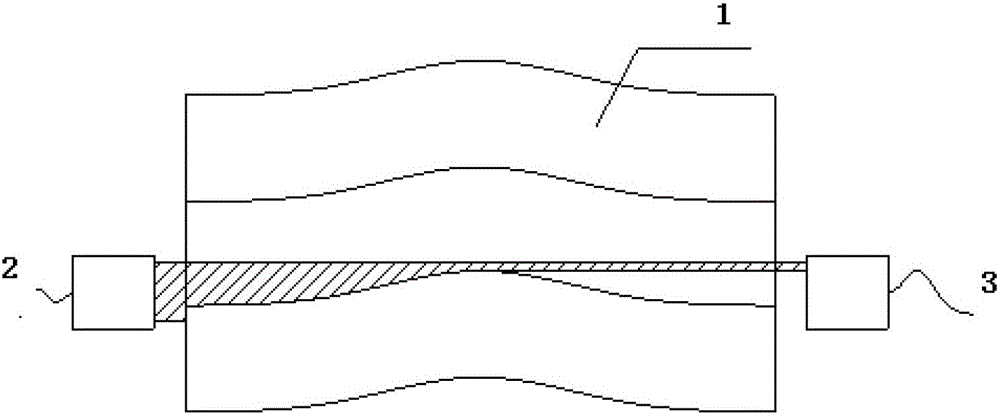
[0042] Such as figure 1 As shown, a cable force measuring device includes a pin shaft 1, a lug plate 5, an axial through hole is opened on the axial center axis of the pin shaft 1, and an optical measurement system is symmetrically placed at both ends of the axial through hole At the transmitting end and the receiving end, the measurement plane of the optical measurement system is coplanar with the axial axis of the pin shaft and the load acting direction, and the lug plate is provided with a limit device connected to the pin shaft.

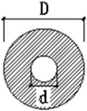
[0043] Such as image 3 As shown, the diameter d of the axial through hole is more than 10mm, and the area of ​​the axial through hole accounts for less than or equal to 12% of the pin shaft area. The pin shaft section moment of inertia with the axial through hole and the pin without the axial through hole The ratio of the moment of inertia of the shaft section is ≥97.5%.

[0044] The resolution of the optical measurement system is less than or equal ...

Embodiment 2

[0057] 1. Calibration of standard test pieces in a factory environment;

[0058] A cable force measurement method includes the following steps:

[0059] S1 preprocesses the pin shaft 1 and the lug plate 5;

[0060] An axial hole is opened at the central axis of the pin shaft, and a limit device is set at the lug plate to connect the pin shaft so that the plane of the laser light curtain and the pulling force direction of the cable are coplanar. The limit device is not limited. The lug plate in this embodiment Setting the limit device to connect the pin shaft specifically includes: two pins are arranged at the pin shaft, two limit small grooves are opened on the lug plate, and the pin and the limit small groove match. In the actual structural force, Existing pin shafts will all rotate freely relative to the lug plate. Since the measuring instruments are all installed at the pin shaft, when the pin shaft rotates, the plane of the laser light curtain and the force direction of the cabl...


PUM

PropertyMeasurementUnit
yield strengthaaaaaaaaaa

Abstract

The invention discloses a method and a device for measuring a cable force. The device comprises a pin shaft and an ear plate, wherein an axial through hole is arranged in the axial axle wire of the pin shaft, two ends of the axial through hole are respectively and symmetrically provided with a transmitting end and a receiving end of an optical measurement system, a measurement plane of the optical measurement system is coplanar with the axial axes of the pin shaft and the action direction of load, and the ear plate is provided with a limit device to be connected with the pin shaft. On the basis that the pin shaft has the characteristics of being even in material and completely and linearly elastic under the stress state, the cable force of an inhaul cable is confirmed by the measurement of the tinny deformation of the pin shaft of a connecting node under the action of the cable force and the linear relationship between the cable force and the deformation. The method and the device provided by the invention are nondestructive testing technologies, thereby being wide in application range.

Description

Technical field [0001] The invention relates to the field of construction detection, in particular to a cable force measurement method and device. Background technique [0002] In the prior art, the main methods of measuring cable force are tension jack measurement method; pressure sensor measurement method; frequency vibration measurement method; electromagnetic measurement method; [0003] The tension jack measurement method, because the pressure gauge itself has the characteristics of rapid pointer deflection, easy deviation, sharp pointer jitter under high pressure, and artificial random errors in readings, so it cannot be used for the cable force after the building structure is formed. Dynamic measurement is also not suitable for long-term clue force measurement. The measured cable force only represents the cable force at the tension end. [0004] Pressure sensor measurement method; [0005] Disadvantages: 1. The cost is too high; 2. It can only measure the tension of the cable...

Claims


Application Information

Patent Timeline
Patent Type & Authority Patents(China)
IPC IPC(8): G01L5/04
Inventor 孙文波周伟坚
Owner SOUTH CHINA UNIV OF TECH
Why Eureka
Try Eureka