Control system for modular multilevel converter and application method of control system

A modular multi-level control system technology, applied in the direction of electrical components, output power conversion devices, etc., can solve the problem of various control tasks, the scale of the control system, and the design and implementation of the modular multi-level converter control system Difficulty and other issues, to achieve the effect of good expansion performance and voltage balance

Active Publication Date: 2013-09-04
ZHEJIANG UNIV
View PDF5 Cites 40 Cited by
  • Summary
  • Abstract
  • Description
  • Claims
  • Application Information

AI Technical Summary

Problems solved by technology

So many sub-modules make the control system very complex in hardware design, and the control tasks are numerous, which brings difficulties to the design and implementation of the modular multilevel converter control system
The conventional control system scheme is: all sub-modules of the modular multilevel converter are managed and controlled by an FPGA. Although this scheme is simple in structure and easy to develop, the number of sub-modules that can be controlled by the control system is severely restricted. On the scale of FPGA
For the main bridge of a modular multilevel converter, the modular design of the main bridge can be realized by cascading different numbers of sub-modules to match different voltage levels and power levels, but the conventional control system scheme However, it is not possible to match different voltage levels and power levels through simple expansion. It is necessary to redesign the hardware platform of the control system and reselect the FPGA
In applications with a large number of sub-modules, it is difficult to select the type of FPGA and develop the control system in the conventional control system solution

Method used


Image

  • Control system for modular multilevel converter and application method of control system
  • Control system for modular multilevel converter and application method of control system
  • Control system for modular multilevel converter and application method of control system

Examples


Embodiment Construction

[0027] The present invention will be further described below in conjunction with the accompanying drawings and specific embodiments.

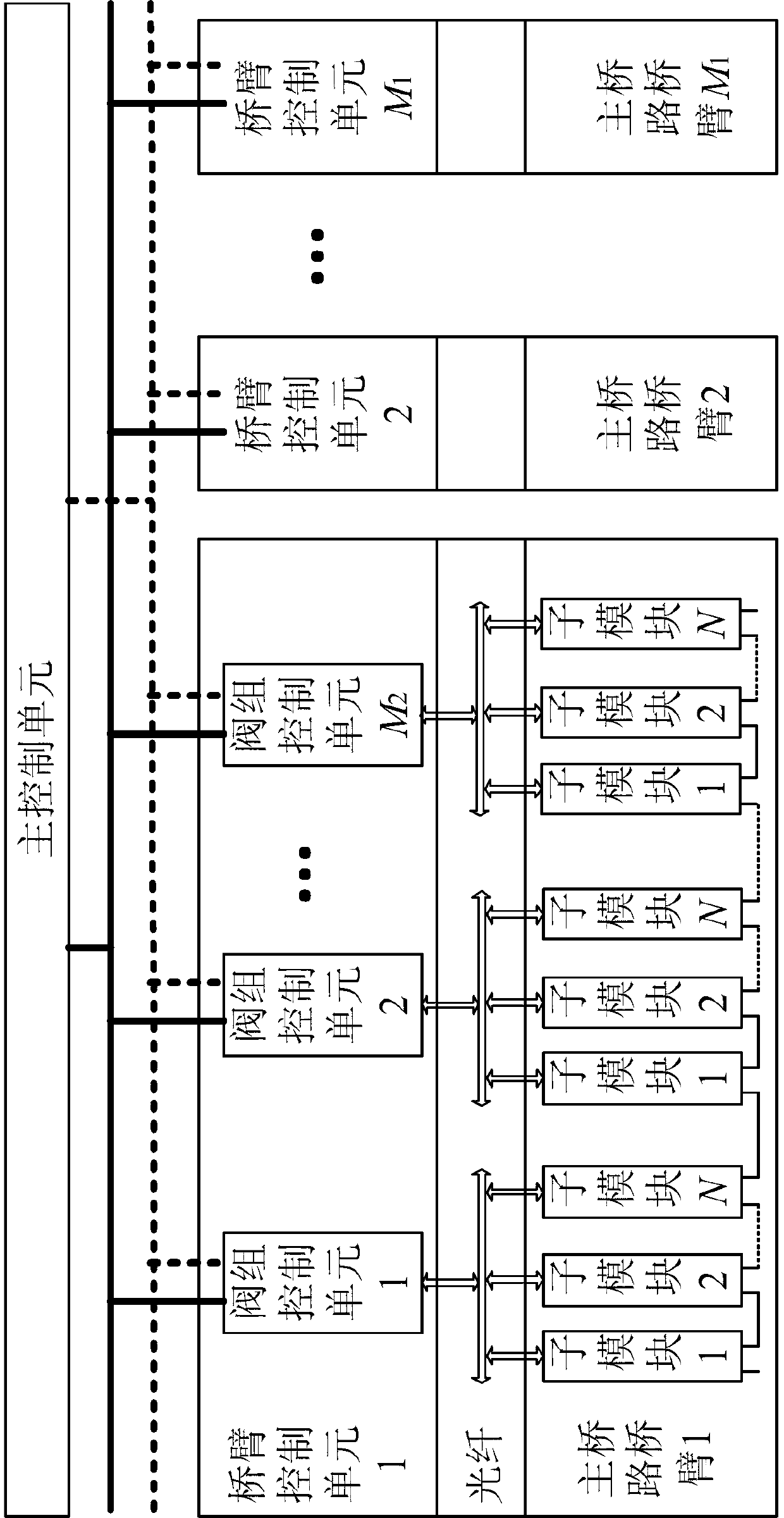
[0028] like figure 1 As shown, the black solid line between the main control unit and the bridge arm control unit represents the high-speed digital bus, the black dotted line represents the communication bus, and the double-headed arrow represents the optical fiber connection between the valve group control unit and the sub-module.

[0029] like figure 1 As shown, a control system of a modular multilevel converter includes a main control unit, M 1 bridge arm control unit (M 1 equal to the number of bridge arms of the modular multilevel converter), a set of high-speed digital buses, and a set of communication buses; each bridge arm control unit can be divided into M 2 Each valve group control unit controls the input, removal, bypass and locking of N sub-modules in the valve group through optical fibers, and realizes electrical isolation from ...


PUM


Abstract

The invention discloses a control system for a modular multilevel converter and an application method of the control system. The control system for the modular multilevel converter comprises a master control unit, M1 bridge arm control units, a group of high-speed digital buses and a group of communication buses, wherein each bridge arm control unit comprises M2 valve group control units; and each valve group control unit is used for controlling the use, the removal, the bypassing and the lockout of sub-modules in a corresponding valve group through an optical fiber, and electrically isolating the sub-modules. A sub-module voltage balancing algorithm for the modular multilevel converter consists of an intra-valve group voltage balancing part and an inter-valve group voltage balancing part. The control system and the application method are used for controlling and managing the use, the removal, the bypassing and the lockout of the sub-modules of the modular multilevel converter to realize the voltage balancing of the sub-modules of the modular multilevel converter, are applied to an application situation where the modular multilevel converter has a great number of sub-modules, and have the characteristics of modular design and high expansibility, and the design difficulty of the control system can be greatly reduced.

Description

technical field [0001] The invention relates to the fields of power electronics technology, measurement and control technology and power system, in particular to a control system design scheme of a modular multilevel converter. Background technique [0002] Flexible DC transmission technology is considered to be an ideal solution for multi-terminal DC transmission, grid-connected renewable energy generation, and asynchronous interconnection of AC systems. Conventional flexible DC transmission technology basically adopts two-level voltage source converter or three-level voltage source converter as its converter topology, which has the disadvantages of high du / dt and large switching loss. Compared with two-level voltage source converters or three-level voltage source converters, modular multilevel converters have high output voltage levels, good harmonic characteristics, modular design, easy expansion, and switching It has the advantages of low loss and other advantages, so i...

Claims


Application Information

Patent Timeline
Patent Type & Authority Applications(China)
IPC IPC(8): H02M1/092
Inventor 周月宾江道灼郭捷梁一桥胡鹏飞林志勇
Owner ZHEJIANG UNIV
Why Eureka
Try Eureka