Method for designing optical fiber bus based on Ethernet passive optical network

A passive optical network and optical fiber bus technology, applied in the direction of optical fiber transmission, electromagnetic network arrangement, bus-type electromagnetic network, etc., can solve the problems of inability to communicate with each other, three-layer switches cannot completely replace routers, and switches cannot recognize IP addresses, etc. Achieve the effect of high data transmission bandwidth and high reliability

Inactive Publication Date: 2013-09-04
慈溪市京慈通信科技有限公司
View PDF5 Cites 1 Cited by
  • Summary
  • Abstract
  • Description
  • Claims
  • Application Information

AI Technical Summary

Problems solved by technology

A Layer 2 switch can only connect computers with IP addresses in the same subnet. If the IP addresses of computers are in different subnets, even if they are connected to the same switch port, they cannot communicate with each other even though they are close at hand, because now The computers communicate with each other through IP addresses, and the switch does not recognize the IP addresses
However, it should be noted that the Layer 3 switch cannot completely replace the router, because it is mainly for communication between VLANs in two different subnets, rather than for complex path selection for data transmission.

Method used


Image

  • Method for designing optical fiber bus based on Ethernet passive optical network
  • Method for designing optical fiber bus based on Ethernet passive optical network
  • Method for designing optical fiber bus based on Ethernet passive optical network

Examples


Embodiment Construction

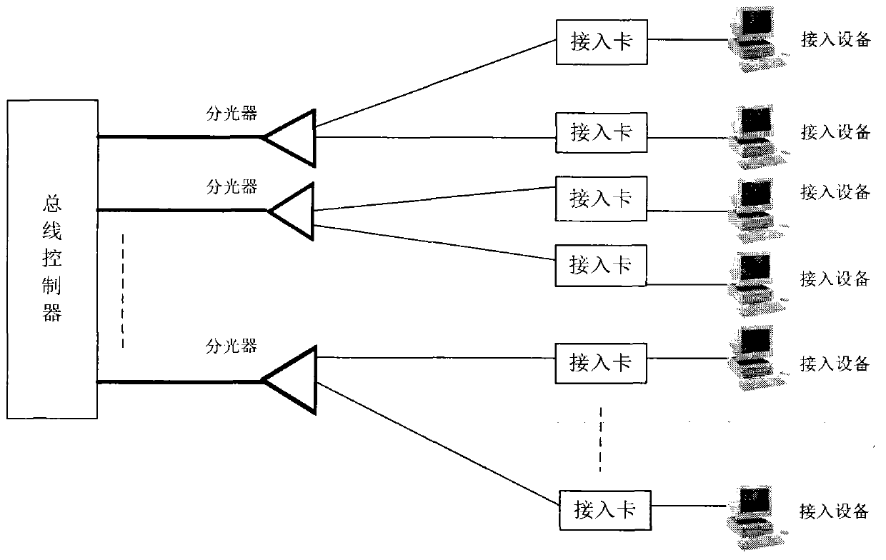
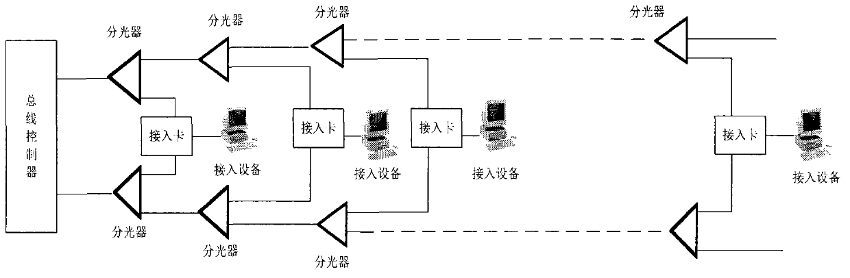
[0039] The present invention has designed a group of devices, and its topological structure is as attached figure 2 , with image 3 , with Figure 4 . As shown, the device consists of four parts: bus controller, optical splitter, optical fiber and access card. The bus controller completes the data exchange and control between the access devices; the optical splitter completes the division of the optical path; the optical fiber is the channel for data transmission; the access card completes the transfer between the bus and the access devices. Any access device can perform broadband data communication with another access device to realize the exchange function of the data bus.

[0040] 1. Bus controller

[0041] Divided into two modes:

[0042] (1) Layer 3 switching mode: It consists of an optical line terminal (OLT) and a layer 3 switch. The connection method is as attached Figure 5 , this mode is suitable for data transmission with large bandwidth. The data from the ac...


PUM


Abstract

The invention relates to a method for designing an optical fiber bus based on an Ethernet passive optical network. The method includes a configuration method of the Ethernet passive optical network, a three-tier exchange mechanism, a topological graph of optical fiber bus design, a bus controller, access units, a photovoltaic conversion module, optical dividers and optical fibers. In the prior art, foreign standards are adopted for all technologies related to the optical fibers, and due to the fact that the technologies and chips used for realizing the technologies belong to an embargo range which the west imposes on China, China can not directly adopt the standards. The novel method replaces an abroad homogeneous technology, and a set of autonomous standard systems of optical fiber bus products is established in China. Therefore, the optical fiber bus technology can be widely applied to the fields of aerospace, aviation, a military industry, an electronic industry and the like.

Description

technical field [0001] The invention belongs to the field of electronic information and communication technology, and relates to a design method and principle of an optical fiber bus based on an Ethernet passive optical network. Background technique [0002] 1. Ethernet Passive Optical Network (EPON) [0003] Ethernet passive optical network is a network that uses optical fiber as the transmission medium and Ethernet protocol as the upper layer transmission protocol. It consists of four parts: Optical Line Terminal (OLT), Optical Network Unit (ONU), Passive Optical Splitter (POS), and Optical Line. The optical fiber line terminal OLT completes the data exchange and control between each access ONU; the optical network unit ONU completes the transfer with the user equipment, and the optical splitter completes the branching of the optical path; the optical fiber is the channel for data transmission; the Ethernet passive optical network It is a new type of broadband access tec...

Claims


Application Information

Patent Timeline
Patent Type & Authority Applications(China)
IPC IPC(8): H04B10/278H04B10/25
Inventor 杜和青
Owner 慈溪市京慈通信科技有限公司
Why Eureka
Try Eureka