

Electrode fixing and locating device for breast impedance imaging
A technology of electrical impedance imaging and positioning device, applied in applications, medical science, sensors, etc., can solve the problems of non-skin contact, waste a lot of time to discharge electrodes, negative impact on imaging quality, etc., to ensure uniformity and reduce model Error, improve the effect of detection effect
- Summary
- Abstract
- Description
- Claims
- Application Information
AI Technical Summary
Problems solved by technology
Method used
Image

Examples
Embodiment 1
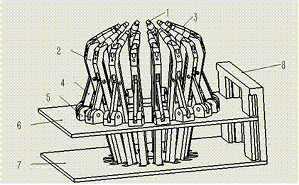
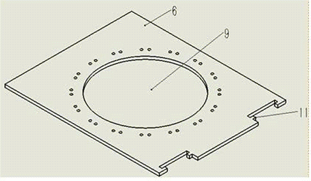
[0033] Embodiment 1: An electrode fixing and positioning device for breast electrical impedance imaging, including a main rod 2, a pull rod 4, a lifting plate 6, a bottom plate 7, and a linear guide module 8; the lifting plate 6 has a main rod radial movable groove 9 , The main rod 2 passes through the main rod radial movable groove 9; one end of the main rod 2 is pivotally hinged with the bottom plate 7, and the other end of the main rod 2 is connected with the electrode 1; the two ends of the pull rod 4 are respectively connected with the main rod 2 and the lifting plate 6 Rotating and hinged, the linear guide rail module 8 is connected with the lifting plate 6 and the bottom plate 7, and the lifting plate 6 is parallel to the bottom plate 7.
[0034] The electrode tip of the electrode 1 in the device of this embodiment surrounds a circle.
[0035] The rotating hinge in the device described in this embodiment refers to the use of a hinge structure to realize the rotation and coop...
Embodiment 2
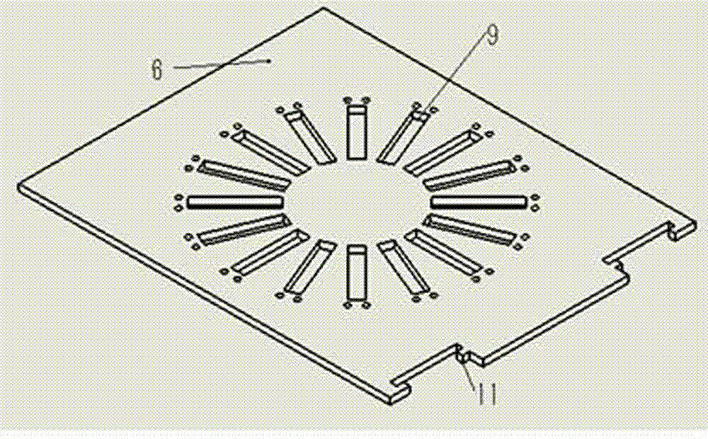
[0043] Embodiment 2: The basic structure of this embodiment is the same as that of Embodiment 1. The difference is: the main rod radial movable groove 9 on the lifting plate 6 is a rectangular slot with a width greater than that of each main rod 2, and the main rod moves radially The grooves 9 are equally spaced on the lifting plate 6; the number of radial movable grooves 9 of the main rod is the same as the number of the main rod 2. The main rod 2 passes through the main rod radial movable groove 9 on the lifting plate 6 and is in the lifting plate 6 6 The center of the circle surrounded by the radial movable groove 9 of the main rod (the center is located on the central axis of the round table enclosed by the main rod 2) is distributed radially; the length of the main rod radial movable groove 9 determines the main rod The radial movement of the rod 2 is surrounded by the radius of the main rod. The width of the main rod’s radial groove 9 determines the non-radial movement ran...
Embodiment 3
[0046] Embodiment 3: The basic structure of this embodiment is the same as that of Embodiment 1 or Embodiment 2. The difference is that: the device includes a vertical sliding shaft 13, which is perpendicular to the bottom plate 7 and fixedly connected, and the lifting plate 6 has The sliding guide sleeve 12 is sleeved on the vertical sliding shaft 13. The vertical sliding shaft 13 is generally one, and the vertical sliding shaft 13 is parallel to the linear guide module 8 (the vertical sliding shaft 13 is connected to the other side of the lifting plate 6 and the bottom plate 7), and the vertical sliding shaft 13 is connected with The simultaneous presence of the linear guide module 8 can make the space enclosed by the electrode 1 on the main pole 2 not have a horizontal deviation, but it is proportional to the expansion and reduction of the distance between the lifting plate 6 and the bottom plate 7 The ground is reduced or enlarged, and the electrodes are accurately position...
PUM
 Abstract
Description
Claims
Application Information