High-speed wire rod combined-type few-rack eventually-forming unit and rolling technology

A high-speed wire rod and combined technology, applied in metal rolling, manufacturing tools, metal rolling, etc., can solve the problems of complex process technology control system and production management, more gear ratios in gearboxes, and increased machinery investment costs. , to achieve the effect of compact equipment structure, less number of rolling mills, and guaranteed wire rod forming quality

Inactive Publication Date: 2013-09-11
CISDI ENG CO LTD
View PDF6 Cites 0 Cited by
  • Summary
  • Abstract
  • Description
  • Claims
  • Application Information

AI Technical Summary

Problems solved by technology

However, the traditional reducing and sizing technology and equipment have the following disadvantages. The number of rolling mills is large, the engineering investment is large, and the pass system is complex, resulting in complex process technology control systems and production management. The gearbox has many speed ratios and complex mechanical structures. , which further increases the cost of mechanical investment, and the large number of speed ratio gears also brings negative effects of low utilization rate. For example, when producing products within the specification range of Φ5.0mm~Φ25.0mm, the speed ratio may only be used in 256 types more than 10 kinds of

Method used


Image

  • High-speed wire rod combined-type few-rack eventually-forming unit and rolling technology
  • High-speed wire rod combined-type few-rack eventually-forming unit and rolling technology
  • High-speed wire rod combined-type few-rack eventually-forming unit and rolling technology

Examples


Embodiment 1

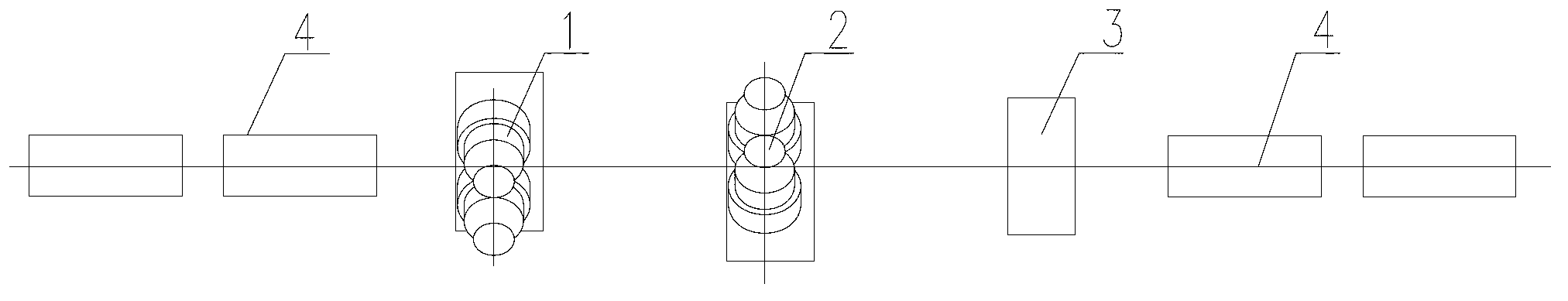
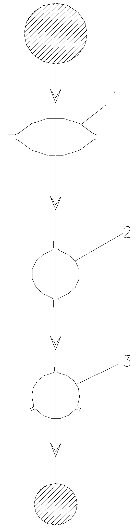
[0029] Embodiment 1: As shown in the figure, the high-speed wire combined type final forming unit with few stands in this embodiment includes the first rolling pass stand 1, the second rolling pass stand 2 and the second rolling pass stand arranged in sequence. Three rolling pass stands 3, the first rolling pass stand 1 includes two work rolls, and the pass formed by the two work rolls is elliptical, and the second rolling pass stand 2 includes Two work rolls, and the pass formed by the two work rolls is circular, and the third rolling pass frame 3 includes three work rolls arranged in 120° equal divisions, and the hole formed by the three work rolls The shape is round. The arrangement of three work rolls at 120° is a professional term for the arrangement of work rolls in the cold rolling industry. Specifically, it means that the round angle of the pass section on each work roll is 120°.

[0030] Since the third rolling pass frame adopts the three-roll pass, compared with the...

Embodiment 2

[0033] Embodiment 2: The rolling process of the high-speed wire combined type final forming unit with few racks in this embodiment, the rolling elongation of the first rolling pass stand 1 is 1.0, and the second rolling pass The rolling elongation of stand 2 is 1.0, the rolling elongation of stand 3 in the third rolling pass is 1.0, and the total rolling elongation of the three rolling passes is 1.0. In this embodiment, the rolling temperature of each rolling pass is controlled at 950°C.

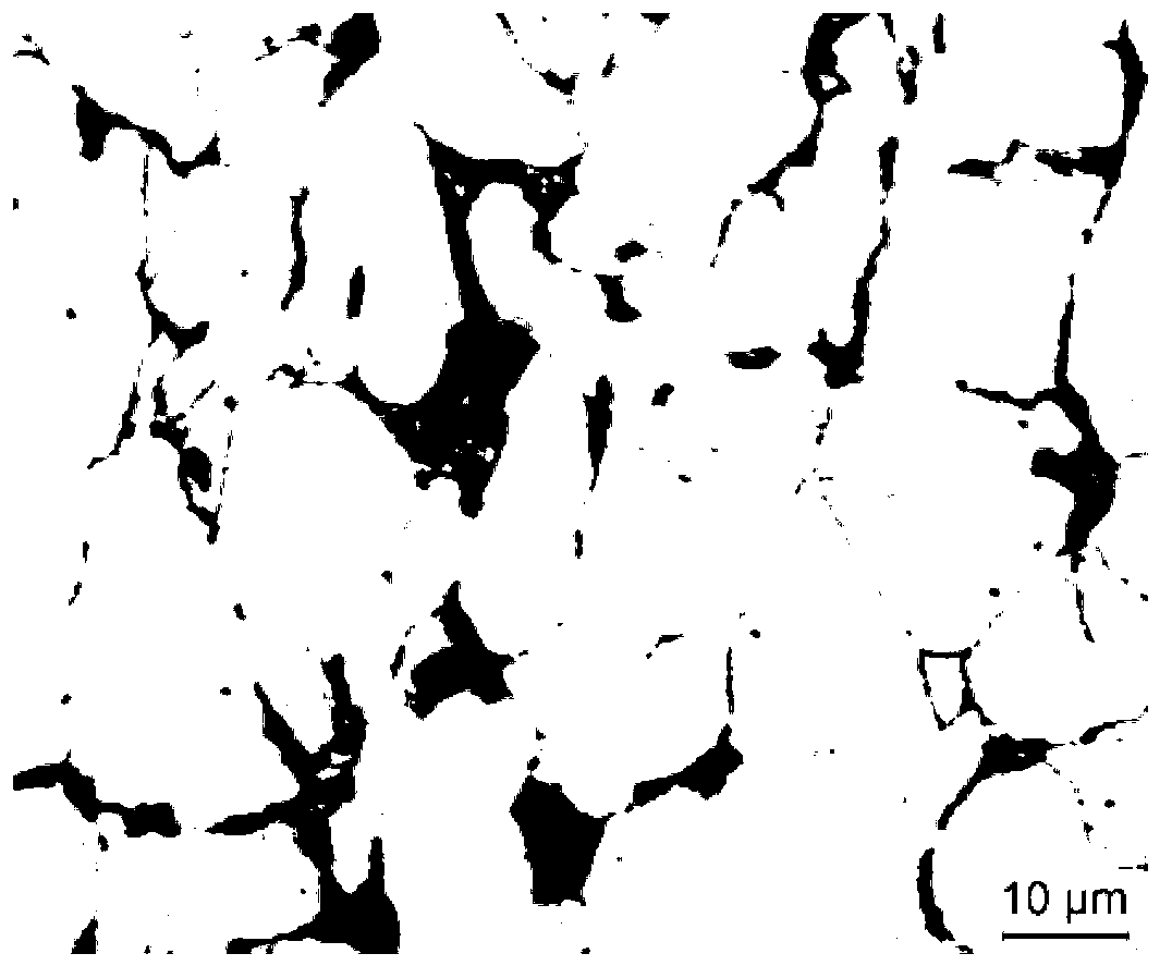
[0034] The microstructure of Q345 obtained by adopting 950°C non-deformation and single-pass large-pressure deformation system (total elongation rate 1.0) and continuous cooling at 1°C / s is shown in Figure 4 , image 3 It is the metallographic diagram of the rolled piece before rolling. It can be seen that when it is not deformed, the structure is ferrite, pearlite and bainite distributed along the grain boundary; through Figure 4 and image 3 In comparison, it can be seen that the micr...

Embodiment 3

[0035] Embodiment 3: The rolling process of the high-speed wire rod combination type final forming unit with few stands in this embodiment, the rolling elongation of the first rolling pass stand 1 is 1.2, and the second rolling pass The rolling elongation of stand 2 is 1.2, the rolling elongation of stand 3 in the third rolling pass is 1.1, and the total rolling elongation of the three rolling passes is 1.6. In this embodiment, the rolling temperature of each rolling pass is controlled at 950°C.

[0036] The Q345 microstructure obtained by adopting 950°C non-deformation and single-pass large-pressure deformation system (total elongation rate 1.6) and continuous cooling at 1°C / s is shown in Figure 5 , Figure 5 The ferrite and pearlite grains in the medium are uniformly distributed, and Figure 5 Tissue ratio Figure 4 It can be seen that the greater the deformation under large pressure, the more conducive to the refinement of the structure, which can improve the mechanical...


PUM


Abstract

The invention discloses a high-speed wire rod combined-type few-rack eventually-forming unit and a rolling technology. The high-speed wire rod combined-type few-rack eventually-forming unit comprises a first rolling pass rack, a second rolling pass rack and a third rolling pass rack. The third rolling pass rack comprises three working rollers which are arranged at equal angles of 120 degrees. The elongation rate of a first rolling pass and the elongation rate of a second rolling pass are respectively 1.0-1.4, and the elongation rate of a third rolling pass is 1.0 to 1.2. The overall rolling elongation rate of the three rolling passes is 1.0 to 1.8. Three-roller hole types are adopted on the third rolling pass rack, the three-roller hole types are beneficial to reducing a broadsiding effect and improving the elongation rate of a rolled piece, deformation and temperature rising are reduced due to the fact that the broadsiding effect is reduced, the stress generated inside the rolled piece is beneficial to deformation of the rolled piece, and pressing on the cross section is more even. Meanwhile, the elongation range of the rolled piece in the three-roller hole types is large, and rolling with different standards within a larger range inside the same hole type can be achieved only with the need of appropriately adjusting a roller gap of the hole types. In addition, compared with a traditional unit, the high-speed wire rod combined-type few-rack eventually-forming unit is few in the number of rolling mills and low in equipment investment.

Description

technical field [0001] The invention relates to a rolling equipment and a rolling process, in particular to a high-speed wire rolling equipment and a rolling process. Background technique [0002] As one of the important products in the iron and steel industry, wire rod is widely used in construction, machinery and metal products industries. In recent years, the output has continued to increase, reaching 25% of China's total steel output in 2012. [0003] As we all know, steel production consumes a lot of energy and has a huge impact on the environment. Under the current increasingly stringent energy and environmental requirements, the contradiction between reducing production energy consumption and improving the performance of steel products is intensifying. [0004] Continuous casting and rolling, hot charging and hot delivery, controlled rolling and controlled cooling can effectively reduce energy consumption, and at the same time, without adding microalloying elements, ...

Claims


Application Information

Patent Timeline
Patent Type & Authority Applications(China)
IPC IPC(8): B21B1/18B21B27/02B21B37/56
Inventor 周民谭成楠陈莹卷闵建军马靳江牛强
Owner CISDI ENG CO LTD
Why Eureka
Try Eureka