Experimental apparatus and experimental method for simulating gas-well annulus pressure carrying and air cutting processes

A technology with annular pressure and experimental methods, which is applied in earthwork drilling, wellbore/well components, measurement, etc., can solve problems such as unclear pressure change law, induced well kick, gas kick, etc., and achieve strong popularization and application The effect of value, reliable performance, and simple structure

Inactive Publication Date: 2013-09-11
SOUTHWEST PETROLEUM UNIV
View PDF4 Cites 18 Cited by
  • Summary
  • Abstract
  • Description
  • Claims
  • Application Information

AI Technical Summary

Problems solved by technology

[0003] In addition, when the drilling process encounters a high-pressure gas layer, a huge pressure difference will be formed between the formation and the bottom of the well, and the original balance between the bottomhole pressure and the formation pressure may be broken, and the natural gas in the formation will enter the wellbore, resulting in gas invasion. happened
Poor control of gas invasion will induce well kick or even lead to blowout
Once a blowout occurs, it will cause huge damage to the reservoir, drilling equipment and the life safety of drilling personnel
[0004] At present, there is no corresponding experimental device and method to simulate the gas well annular pressure and gas invasion process, and the pressure change law in the annular space is still unclear

Method used


Image

  • Experimental apparatus and experimental method for simulating gas-well annulus pressure carrying and air cutting processes
  • Experimental apparatus and experimental method for simulating gas-well annulus pressure carrying and air cutting processes
  • Experimental apparatus and experimental method for simulating gas-well annulus pressure carrying and air cutting processes

Examples


Embodiment 1

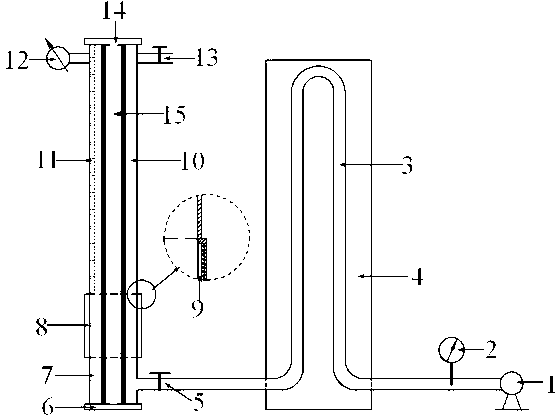
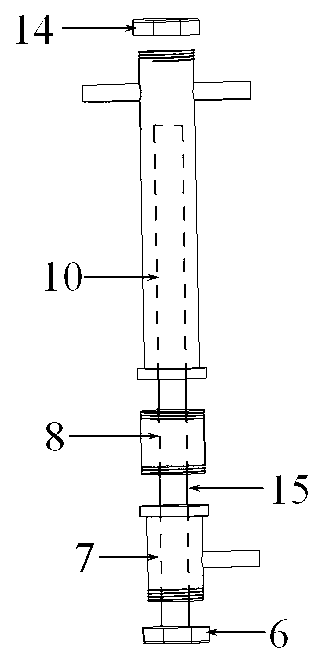
[0022] Example 1: When simulating the process of gas well annulus under pressure, first install the central cylinder, connect the lower sealing cover 6 with the lower air intake cylinder 7, and the lower sealing cover 6 and the central column 15 form an integral structure, and the upper end of the lower air intake cylinder 7 It is connected with the core holding cylinder 8, and the rubber sleeve 9 is placed on the inner wall of the core holding cylinder 8. The thickness of the rubber sleeve 9 is just the difference between the inner diameter of the core holding cylinder 8 and the inner diameter of the upper pressure measuring cylinder 10, so that the pad The inner diameter of the core holding cylinder 8 with the rubber sleeve 9 is the same as the inner diameter of the upper pressure measuring cylinder 10 and the lower air inlet cylinder 7, and then the polished annular core is placed outside the center column 15 and placed in the core holding cylinder 8 Fixed, the other end of ...

Embodiment 2

[0023]Example 2: When simulating the gas invasion process, first install the central cylinder, connect the lower sealing cover 6 with the lower air intake cylinder 7, and the lower sealing cover 6 and the central column 15 form an integral structure, and the upper end of the lower air intake cylinder 7 is connected to the core clamp The holding cylinder 8 is connected, and the rubber sleeve 9 is placed on the inner wall of the core holding cylinder 8. The thickness of the rubber sleeve 9 is just the difference between the inner diameter of the core holding cylinder 8 and the inner diameter of the upper pressure measuring cylinder 10, so that the rubber sleeve is cushioned. The inner diameter of the core holding cylinder 8 of 9 is the same as the inner diameter of the upper end pressure measuring cylinder 10 and the lower end air inlet cylinder 7, the other end of the rock core holding cylinder 8 is connected with the upper end pressure measuring cylinder 10, and the upper end pr...


PUM


Abstract

The invention relates to an experimental apparatus and an experimental method for simulating gas-well annulus pressure carrying and air cutting processes. A central cylinder is the key structure of the experimental apparatus, and comprises a rock-core clamping cylinder, a rubber sleeve, an upper sealing cover, a lower sealing cover, a central column, an upper-end pressure-detecting cylinder and a lower-end air inlet cylinder. A rock core is disposed in the rock-core clamping cylinder. Annulus protective liquid with certain height is injected into the central cylinder from a valve II, and the whole device is guaranteed to be in a sealing state. Air is injected into the central cylinder through an air compressor to realize simulation of a gas-well annulus pressure carrying process. In addition, on the condition that the rock core is not mounted, experimental to-be-tested liquid with certain height is injected into the central cylinder, and an air cutting process can be simulated. The experimental apparatus is simple in structure, convenient to assemble and reliable in performance, two different experimental processes can be simulated by one experimental device, and high popularization and application value is provided.

Description

technical field [0001] The invention relates to an experimental device and method for simulating the gas well annulus pressure and gas invasion process in the production process of oil and gas wells. Background technique [0002] The so-called annular pressure mainly refers to the phenomenon that the annular pressure at the wellhead returns to the pressure level before the pressure relief after pressure relief. There are four main reasons for the formation of annular pressure: the first is the annular pressure caused by various human factors (including gas lift, thermal recovery management, monitoring of annular pressure, etc.); the second is the temperature change of the casing annular And the annulus pressure caused by the deformation of the fluid and the expansion string caused by the bulging effect; the third is the annulus pressure caused by the gas channeling caused by the failure of the oil casing string (especially the failure of the threaded connection and the seal ...

Claims


Application Information

Patent Timeline
Patent Type & Authority Applications(China)
IPC IPC(8): E21B47/10
Inventor 朱红钧林元华戚兴冯光曾德智韩青华周莹赵洪南
Owner SOUTHWEST PETROLEUM UNIV
Why Eureka
Try Eureka