Rolling friction or suspension friction impact excavating method and antiabrasion impact excavator for implementing the same

A technology of rolling friction and dynamic impact, applied in cutting machinery, driving devices, mining equipment, etc., can solve the problems of hydraulic cylinder damage, increase leakage, increase gap, etc., to prevent damage and widening of reaction force. The effect of righting width and increasing righting strength

Active Publication Date: 2013-09-11
刘素华
View PDF6 Cites 12 Cited by
  • Summary
  • Abstract
  • Description
  • Claims
  • Application Information

AI Technical Summary

Problems solved by technology

The power part adopts a hydraulic cylinder, in which there is sliding friction between the piston and the cylinder body, and the frictional resistance is large, which causes severe wear of the sealing plug and increases the gap between the piston and the cylinder body, thereby increasing the leakage, and at the same time Increased energy consumption affects the performance of the equipment; in this invention, a hydraulic cylinder is used to drive the working parts to impact, and the impact frequency is low and the speed is slow, so it cannot achieve the effect of using a mechanical transmission mechanism, such as a crank mechanism with high frequency impact; its working parts Installed at the end of the hydraulic cylinder, when the hydraulic cylinder drives the working parts to extend or retract along its axial direction, there are still problems such as swaying or swaying of the working parts, which affects the impact effect; since the hydraulic cylinder rod has no auxiliary guide device, it is powerful during mining. The impact reaction force makes the working parts seriously separate from the hydraulic cylinder, so that the sliding friction is concentrated on the local wear of the hydraulic cylinder, causing serious damage to the hydraulic cylinder and making the equipment unable to operate normally

Method used


Image

  • Rolling friction or suspension friction impact excavating method and antiabrasion impact excavator for implementing the same
  • Rolling friction or suspension friction impact excavating method and antiabrasion impact excavator for implementing the same
  • Rolling friction or suspension friction impact excavating method and antiabrasion impact excavator for implementing the same

Examples


Embodiment 1

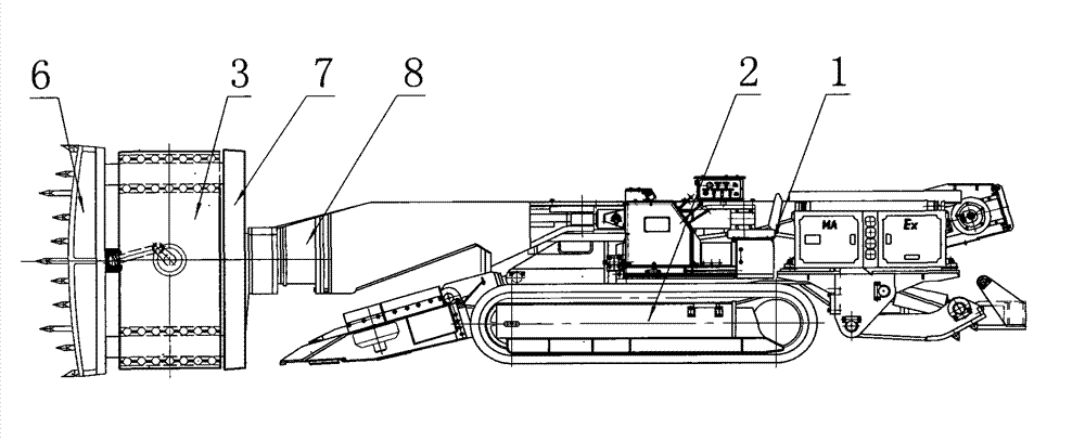
[0541] like Figure 1 to Figure 3 As shown, an anti-wear impact mining machine, the rolling friction impact mining machine includes a fuselage 1, a walking part 2, a reciprocating impact part 3, etc., the reciprocating impact part 3 includes a guide device 5, an impact drive device 4, etc., the guide device 5 Separated from the impact drive device 4, the guide device 5 includes an impact guide 5.1, a guide rolling body 5.3, a guide support 5.2, etc., the guide roll 5.3 is arranged between the guide support 5.2 and the impact guide 5.1, and the impact guide 5.1 The impact head 6 is set at one end and the other end is set to prevent the impact head 6 from being separated from the guide device 5, the impact drive device 4 and / or the fuselage 1 due to gravity imbalance. The counterweight 7, the impact head 6 is connected with the impact guide 5.1, The impact drive device 4 includes a power impact part 4.1, etc., the power impact part 4.1 drives the impact guide part 5.1 to recipro...

Embodiment 2

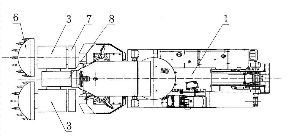
[0556] like Figure 4 to Figure 5 As shown, an anti-wear impact mining machine, the rolling friction impact mining machine includes a fuselage 1, a walking part 2, a reciprocating impact part 3, etc., the reciprocating impact part 3 includes a guide device 5, an impact drive device 4, etc., the guide device 5 Integrated with the impact drive device 4, the guide device 5 includes an impact guide 5.1, a guide rolling body 5.3, a guide support 5.2, etc., the guide roll 5.3 is arranged between the guide support 5.2 and the impact guide 5.1, and the impact guide Impact heads 6 etc. are arranged at both ends of 5.1, the impact head 6 and the impact guide 5.1 are integrated, the impact drive device 4 includes the power impact 4.1, etc., the power impact 4.1 drives the impact guide 5.1 to reciprocate, and the impact guide 5.1 drives The impact head 6 impacts the coal wall or rock wall to realize the mining and falling of materials. The power impact part 4.1 and the impact guide part 5...

Embodiment 3

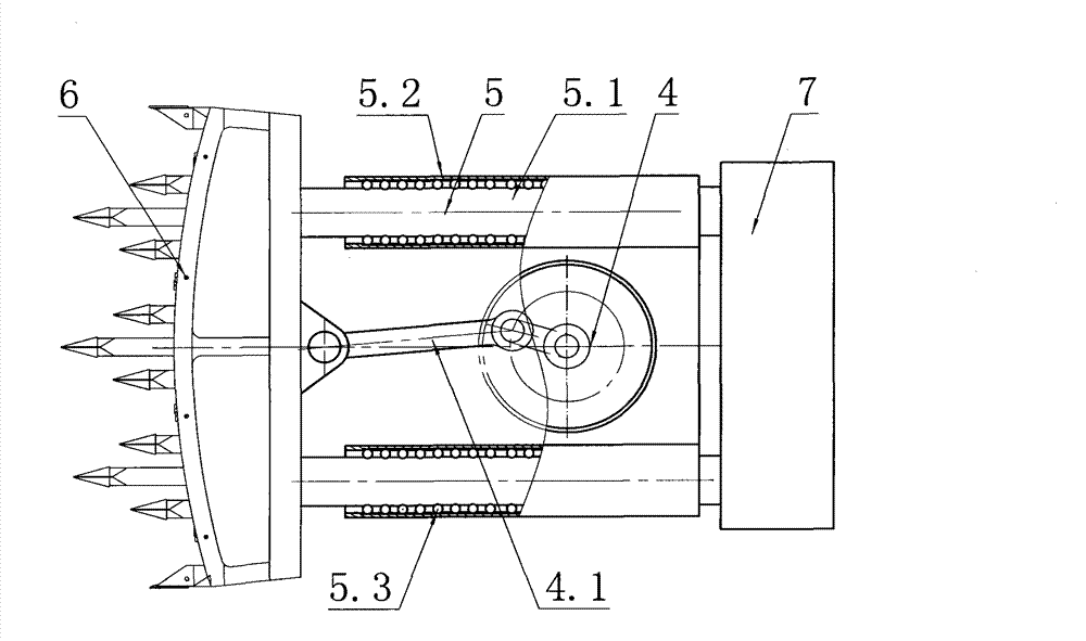
[0568] like Figure 6 to Figure 7 As shown, an anti-wear impact mining machine includes a fuselage 1, a walking part 2, a lifting device 9, a reciprocating impact part 3, etc., the reciprocating impact part 3 includes a guide device 5, an impact drive device 4, etc., and the impact drive device 4 includes Crank impact drive device 4.2 or hydraulic impact drive device or pneumatic impact drive device, etc., crank impact drive device 4.2 or hydraulic impact drive device or pneumatic impact drive device includes power impact member 4.1, etc., guide device 5 includes guide support member 5.2, impact guide Part 5.1, guide rolling body 5.3, etc., the guide rolling body 5.3 is set between the guide support 5.2 and the impact guide 5.1, the impact head 6 is set at one end of the impact guide 5.1 and the other end is set to prevent the impact head 6 from being separated due to gravity imbalance The guiding device 5, the impact driving device 4, the lifting device 9 and / or the counterwe...


PUM


Abstract

The invention relates to a rolling friction or suspension friction impact excavating method and an antiabrasion impact excavator for implementing the same. The antiabrasion impact excavator includes a reciprocating impact part, which consists of an impact drive device, a rolling reciprocating device and an impact head. The rolling reciprocating device comprises a friction body, a friction body support, an impact guide element and a limit structure. The friction body is arranged between the friction body support and the impact guide element and is disposed at the limit structure to form a rolling guide. The impact drive device is equipped with an anti-breakoff mechanism. The excavator is also provided with a rotary power buffering device and a structure buffering device, so that the impact head can make rolling friction or suspension friction reciprocating motion under support of the impact guide element, the damage caused by an anti-breakoff force to a power drive device and a rolling path guiding device can be prevented, and the influence of a reciprocating impact part's impact shock on the excavator body and other parts can be avoided. Therefore, stability of the whole excavator can be improved, and the service life can be prolonged.

Description

technical field [0001] The invention belongs to the field of machinery, and is particularly suitable for a rolling friction or suspension friction impact mining method in the mining field and an anti-wear impact mining machine implementing the method. Background technique [0002] Roadheaders and shearers are mainly used in the excavation of bridges, culverts and tunnels of railways and highways, as well as mechanized mining of mineral materials. The existing widely used mining equipment is mostly drilling-milling cutting-type roadheaders and rolling-milling shearers. The principle is to drill and mill or roll mill the coal seam or rock formation through the pick teeth arranged on the outer surface of the front part of the cutting head. Since the cutting head produces a large rotational force during drilling and milling or rolling milling, it will have a greater impact on the rotating shaft. Large twisting force will cause serious damage to the rotating shaft and reduce the ...

Claims


Application Information

Patent Timeline
Patent Type & Authority Applications(China)
IPC IPC(8): E21C25/02E21C35/08E21C25/04E21C35/04E21C31/02E21C31/08E21D9/10
CPCE21D9/1026E21C27/28E21C27/46E21D9/106
Inventor 刘素华
Owner 刘素华
Why Eureka
Try Eureka