Rigid-flexible combination gob-side entry retaining method and rigid-flexible combination gob-side entry retaining device by aid of roadside supports

A technology of roadside support and combination of rigidity and flexibility, which is used in shaft equipment, earthwork drilling, wellbore lining, etc. The effect of stability, improvement of working environment, and simplification of construction process

Active Publication Date: 2013-09-11
SHANDONG UNIV OF SCI & TECH
View PDF5 Cites 8 Cited by
  • Summary
  • Abstract
  • Description
  • Claims
  • Application Information

AI Technical Summary

Problems solved by technology

However, the construction process in the filling body construction process is complicated, the underground roadway filling system and the production system interact with each other, and the roadway retention speed is very slow; at the same time, the support strength of the filling body is limited, and the effect of roadway protection under high stress is not good.

Method used


Image

  • Rigid-flexible combination gob-side entry retaining method and rigid-flexible combination gob-side entry retaining device by aid of roadside supports
  • Rigid-flexible combination gob-side entry retaining method and rigid-flexible combination gob-side entry retaining device by aid of roadside supports
  • Rigid-flexible combination gob-side entry retaining method and rigid-flexible combination gob-side entry retaining device by aid of roadside supports

Examples


Embodiment Construction

[0020] The present invention provides a rigid-flexible roadside support method and device for gob-side entry retaining. In order to make the purpose, technical solution and effect of the present invention clearer and clearer, the present invention will be further described in detail below. It should be understood that the specific embodiments described here are only used to explain the present invention, not to limit the present invention.

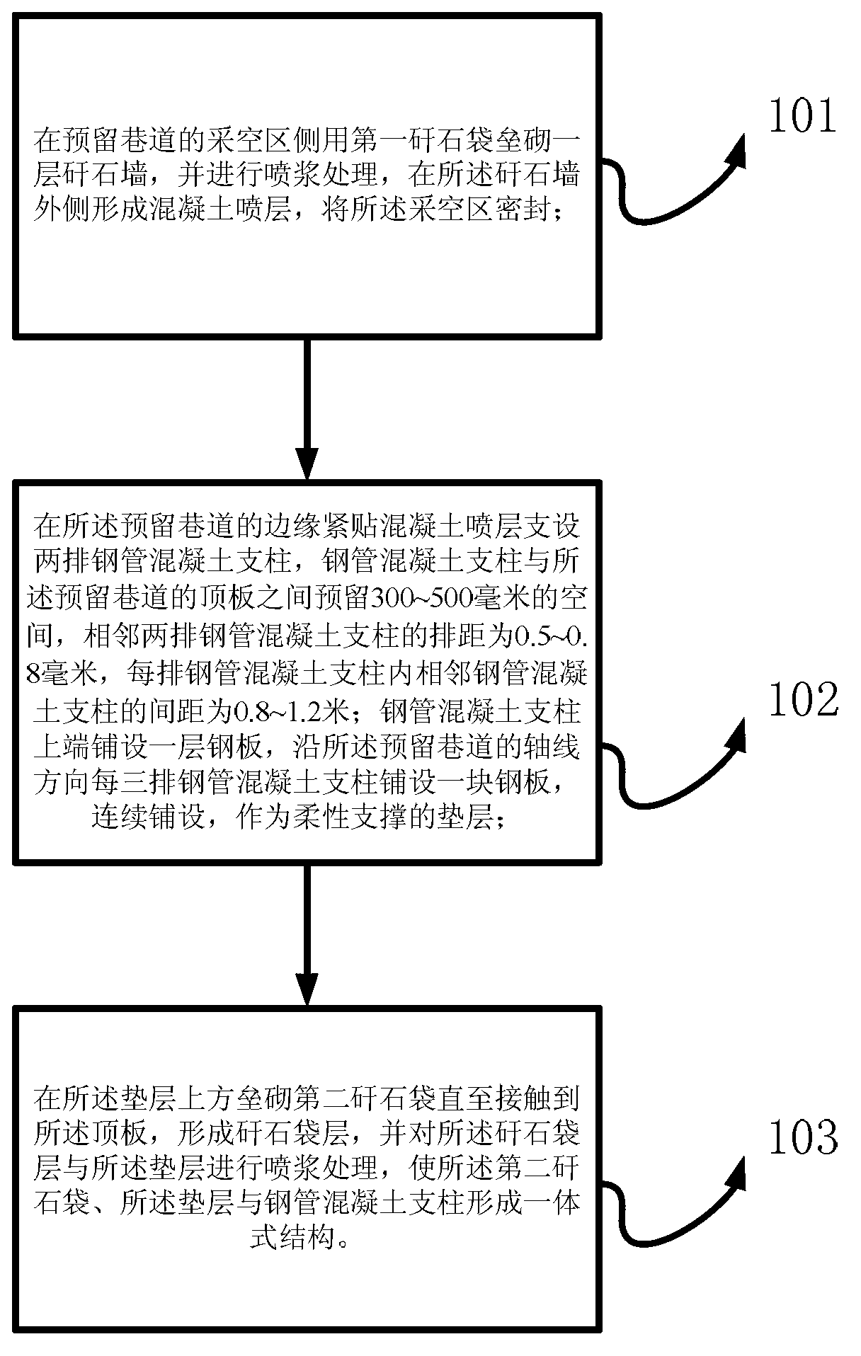
[0021] The invention provides a rigid-flexible roadside support method for gob-side entry retention, such as figure 1 As shown, it includes the following steps:

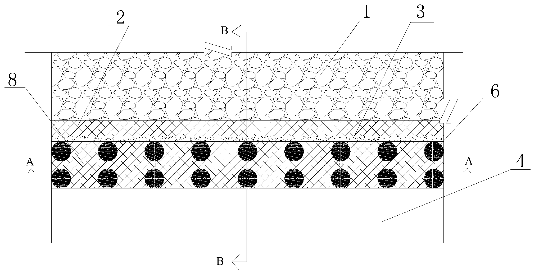
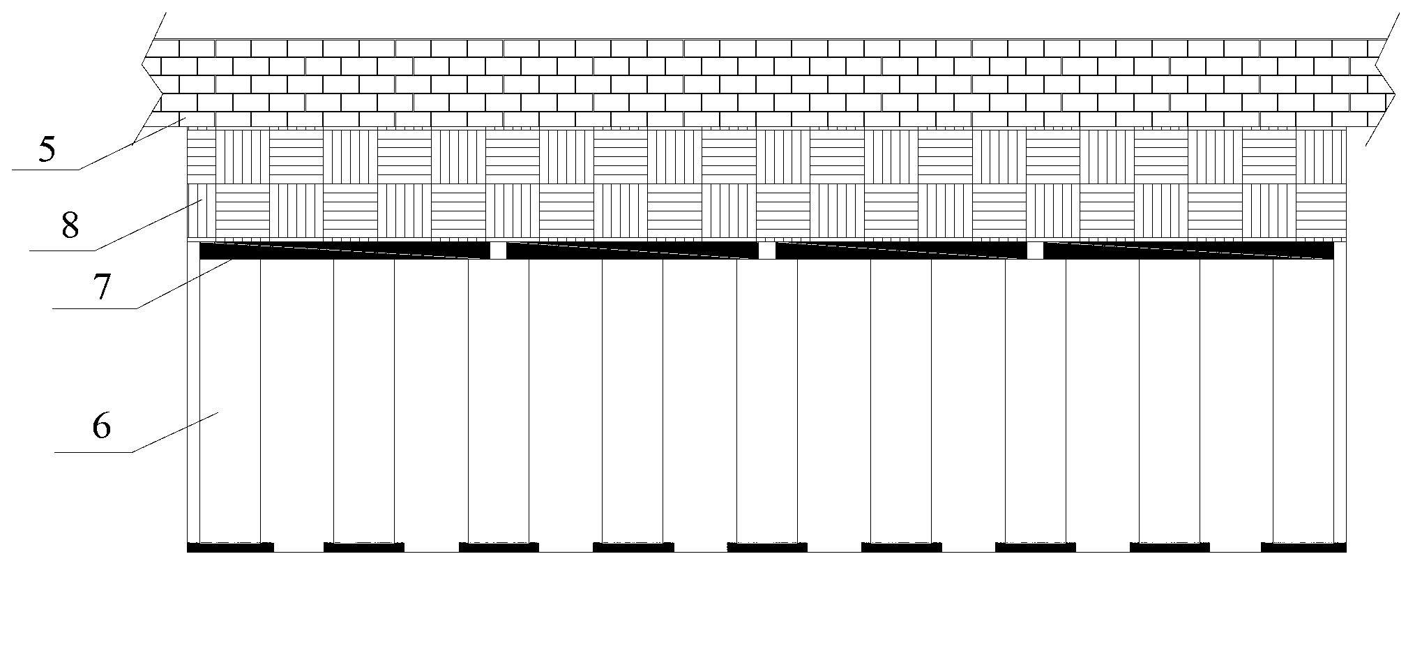
[0022] Step 101: Build a layer of gangue wall with the first gangue bag on the side of the goaf of the reserved roadway, and perform spraying treatment to form a concrete spray layer on the outside of the gangue wall, and seal the goaf;

[0023] Step 102: Set up two rows of concrete-filled steel pipe pillars close to the concrete sprayed layer on the edge of the reserved roadway...


PUM


Abstract

The invention discloses a rigid-flexible combination gob-side entry retaining method and a rigid-flexible combination gob-side entry retaining device by the aid of roadside supports. The rigid-flexible combination gob-side entry retaining method includes building a layer of gangue wall by first gangue bags on a gob side of a reserved roadway to seal a gob; erecting two rows of pillars made of concrete-filled steel tubes at the edge of the reserved roadway, enabling the two rows of pillars to cling to a concrete sprayed layer, laying a steel plate on each three rows of pillars made of concrete-filled steel tubes along the axial direction of the reserved roadway, and continuously laying the steel plates to form a flexible supporting cushion; laying second gangue bags on the cushion until the laid gangue bags are in contact with a top plate to form a gangue bag layer, and performing spouting on the gangue bag layer and the cushion so as to form an integral structure comprising the second gangue bags, the cushion and the pillars made of the concrete-filled steel tubes. The rigid-flexible combination gob-side entry retaining method and the rigid-flexible combination gob-side entry retaining device have the advantages that a flexible yielding effect of the gangue bags and a high-strength support effect of the pillars made of the concrete-filled steel tubes are combined with each other by the structure, accordingly, the rigid-flexible combination gob-side entry retaining method and the rigid-flexible combination gob-side entry retaining device are particularly suitable for gob-side entry retaining engineering in deep and high-stress states, a construction process of the gob-side entry retaining method is simple, the gob-side entry retaining speed can be effectively increased, and an operating environment in the roadway is improved.

Description

technical field [0001] The invention relates to the field of gob-side entry retention in a thin coal seam under a deep high-stress state, in particular to a rigid-flexible roadside support method and a device for gob-side entry retention. Background technique [0002] Gobside retaining is an important technology in the mining system without coal pillars. It effectively solves the technical problems of Y-shaped ventilation and control of gas overrun in the working face. It can also reduce the amount of roadway excavation and rationally develop coal resources. According to the analysis of the existing coal pillar-free mining system, the gob-side retaining can generally increase the coal recovery rate in the mining area by 10-20%, and reduce the roadway excavation rate by 25-33%. [0003] The gob-side retaining technology is mainly to arrange a reasonable roadside support on the side of the gob behind the working face to achieve the purpose of retaining the roadway. The roadsid...

Claims


Application Information

Patent Timeline
Patent Type & Authority Applications(China)
IPC IPC(8): E21D11/05E21D11/14
Inventor 黄万朋郭忠平崔海峰申玉三梁赛江王军亓宪寅
Owner SHANDONG UNIV OF SCI & TECH
Why Eureka
Try Eureka