Double-stage variable-speed oppositely-rotating axial flow pump flow passage component for water spraying propelling

A water jet propulsion and flow-passing component technology, which is applied in the field of pump flow-flow components, can solve the problems of narrow high-efficiency range, poor anti-cavitation performance, impeller corrosion and damage of axial flow pumps, etc. Good chemical performance and wide operating range

Inactive Publication Date: 2013-09-11
JIANGSU UNIV OF SCI & TECH
View PDF8 Cites 19 Cited by
  • Summary
  • Abstract
  • Description
  • Claims
  • Application Information

AI Technical Summary

Problems solved by technology

[0004] Due to the large thrust required by the axial-flow water jet propulsion pump, the relative flow head is relatively high, and the axial-flow pump is a low-lift pump. The traditional axial-flow pump design has poor anti-cavitation performance, resulting in large noise and vibration. And the impeller will be damaged by corrosion, resulting in a decrease in pump performance
In addition, the high-efficiency zone of the axial flow pump is very narrow, and severe vibration will occur under low flow conditions
Obviously, single-stage or multi-stage axial flow pumps designed by traditional design methods cannot meet the requirements of modern high-performance ships with good anti-cavitation performance, high stability, and wide operating range.

Method used


Image

  • Double-stage variable-speed oppositely-rotating axial flow pump flow passage component for water spraying propelling

Examples


Embodiment 1

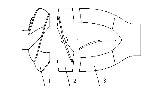
[0017] From the water inlet to the water outlet, the primary impeller 1, secondary impeller 2 and guide vane 3 are installed in sequence. Upper; the speed n of the first stage impeller 1 1 with secondary impeller 2 speed n 2 than n 1 :n 2 =1, the rotation direction of the primary impeller 1 is opposite to that of the secondary impeller 2; the primary impeller 1 is in the form of an inducer, the hub is conical, the smaller end of the hub is the water inlet, and the diameter ratio of the inlet hub is d h : D =0.25, outlet hub diameter ratio d h : D =0.4; the number of blades Z of first stage impeller 1 1 With secondary impeller 2 blade number Z 2 are mutually prime numbers, Z 1 = 2, Z 2 = 3; first-stage impeller 1 cascade denseness s = 1.5; axial clearance S between first-stage impeller 1 and secondary impeller 2, and between secondary impeller 2 and guide vane 3 is 10% of impeller outer diameter D. The device is driven separately by two impellers and two motors to reali...

Embodiment 2

[0019] From the water inlet to the water outlet, the primary impeller 1, secondary impeller 2 and guide vane 3 are installed in sequence, the primary impeller 1, secondary impeller

[0020] The centerlines of wheel 2 and guide vane 3 are on the same straight line and are respectively installed on different shafts; the speed n of the first stage impeller 1 1 with secondary impeller 2 speed n 2 than n 1 :n 2 =1.5, the first-stage impeller 1 and the secondary impeller 2 rotate in the opposite direction; the first-stage impeller 1 is in the form of an inducer, the hub is conical, the smaller end of the hub is the water inlet, and the diameter ratio of the inlet hub is d h : D =0.3, outlet hub diameter ratio d h : D =0.5; the number of blades Z of first stage impeller 1 1 With secondary impeller 2 blade number Z 2 are mutually prime numbers, Z 1 = 2, Z 2 = 5; first-stage impeller 1 cascade density s = 2.25; the axial gap S between the first-stage impeller 1 and the secondary...

Embodiment 3

[0022] From the water inlet to the water outlet, the primary impeller 1, secondary impeller 2 and guide vane 3 are installed in sequence, the primary impeller 1, secondary impeller

[0023] The centerlines of wheel 2 and guide vane 3 are on the same straight line and are respectively installed on different shafts; the speed n of the first stage impeller 1 1 with secondary impeller 2 speed n 2 than n 1 :n 2 =2, the rotation direction of the primary impeller 1 is opposite to that of the secondary impeller 2; the primary impeller 1 is in the form of an inducer, the hub is conical, the smaller end of the hub is the water inlet, and the diameter ratio of the inlet hub is d h : D =0.35, outlet hub diameter ratio d h : D =0.6; the number of blades Z of first stage impeller 1 1 With secondary impeller 2 blade number Z 2 are mutually prime numbers, Z 1 = 3, Z 2 = 5; first-stage impeller 1 cascade denseness s = 3; the axial gap S between the first-stage impeller 1 and the seconda...


PUM


Abstract

The invention discloses a double-stage variable-speed oppositely-rotating axial flow pump flow passage component for water spraying propelling. A primary-stage impeller is in an inducer mode. The rotating direction of the primary-stage impeller is opposite to the rotating direction of a secondary-stage impeller. The rotating speed of the primary-stage impeller and the rotating speed of the secondary-stage impeller are different so as to meet the cavitation performance requirement and the lift efficiency requirement respectively. The ratio of the rotating speed n1 of the primary-stage impeller to the rotating speed n2 of the secondary-stage impeller is between 1 and 2. The boss diameter ratio dh to D of the primary-stage impeller is between 0.25 and 0.6. According to the double-stage variable-speed oppositely-rotating axial flow pump flow passage component for water spraying propelling, a double-stage variable-speed oppositely-rotating axial flow pump is good in cavitation resistant performance, high in lift efficiency and compact in structure, expands the use range of a traditional axial flow pump, and is applicable to the water spraying propelling fields with the operating requirements of good cavitation resistant performance, high lift efficiency, compact structures and the like.

Description

technical field [0001] The invention belongs to a water jet propulsion device, in particular to a flow-passing part of a pump. Background technique [0002] Usually the axial flow water jet propulsion pump is the most widely used form of water jet propulsion. At present, its design theory and design method mainly refer to the design theory of vane pump, but the operating environment of axial flow water jet propulsion pump is completely different from that of axial flow pump. Due to the needs of high-performance ship operation, the axial-flow water jet propulsion pump requires good anti-cavitation performance, high stability and wide operating range. [0003] So far, the design method of axial flow pumps in my country still follows the design theory of the former Soviet Union, that is, the lift method based on the aerodynamic characteristics of a single airfoil or the arc method based on the 0-thickness airfoil cascade. The so-called lift method is to correct the aerodynam...

Claims


Application Information

Patent Timeline
Patent Type & Authority Applications(China)
IPC IPC(8): F04D29/18B63H11/08
Inventor 倪永燕潘希伟潘中永刘为民
Owner JIANGSU UNIV OF SCI & TECH
Why Eureka
Try Eureka