
Measurement method of temperature coefficient of photoelectric receiver based on dual acousto-optic frequency shifting

A photoelectric receiver and acousto-optic frequency shifter technology, applied in the field of laser applications, can solve the temperature characteristic analysis and experimental test of the electrical signal processing circuit without testing, without considering the temperature drift error of the electrical signal processing circuit, and without a photoelectric receiver And other issues

Active Publication Date: 2016-04-27
HARBIN INST OF TECH
View PDF6 Cites 0 Cited by
  • Summary
  • Abstract
  • Description
  • Claims
  • Application Information

AI Technical Summary

Problems solved by technology

However, this literature only considered the photodetector in the analysis, and did not consider the temperature drift error introduced by the electrical signal processing circuit as the temperature changes
[0004] At present, the research on the temperature characteristics of the photoelectric receiver only analyzes the temperature characteristics of the photodetection device in the photoelectric receiver. There is no analysis and experimental test of the temperature characteristics of the electrical signal processing circuit of the photoelectric receiver. Test the temperature characteristics of the photoelectric receiver when the input interference beat frequency is different
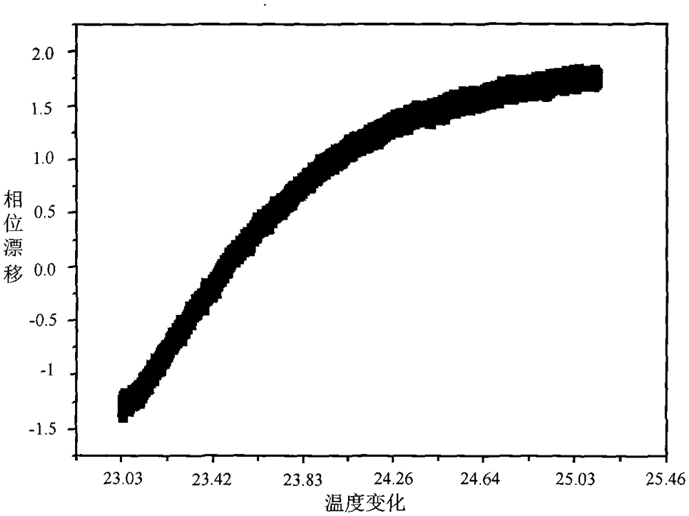
In actual use, the electrical signal processing circuit is affected by temperature so that the output signal will have a certain phase drift with temperature changes, and when the input optical beat frequency is different, the output signal will also have a certain phase drift. Ignoring this part of the error will affect Test Accuracy of Heterodyne Interferometry System

Method used


Image

  • Measurement method of temperature coefficient of photoelectric receiver based on dual acousto-optic frequency shifting
  • Measurement method of temperature coefficient of photoelectric receiver based on dual acousto-optic frequency shifting

Examples


Embodiment Construction

[0024] The examples of the present invention will be described in detail below in conjunction with the accompanying drawings.

[0025] A method for testing the temperature coefficient of a photoelectric receiver based on double acousto-optic frequency shifting, the steps of the method are as follows:

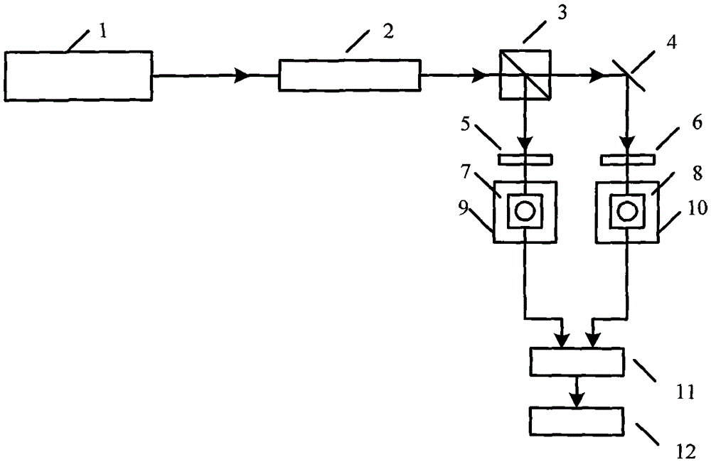
[0026] (1) Put the standard photoelectric receiver 7 into the temperature-adjustable incubator A9, and put the photoelectric receiver 8 to be tested in the temperature-adjustable incubator B10. The temperature stability of the incubators A and B can reach ±0.1 °C, has no effect on the phase stability of the standard photoelectric receiver 7 and the photoelectric receiver 8 to be tested;

[0027] (2) The single-frequency laser 1 emits a beam of laser light, and after passing through the double acousto-optic frequency shifter 2, it becomes a beam including frequencies v 1 and v 2 The dual-frequency laser beam, the polarization directions are mutually orthogonal linearly polarize...


PUM


Abstract

The invention belongs to a laser application technology, and relates to a photoelectric receiver temperature coefficient test method based on double-acousto-optical frequency shift. The method includes using a single-frequency laser as a light source, outputting a double-frequency laser beam after the single-frequency laser passes a double-acousto-optical frequency shifter, utilizing a non-polarized beam splitting prism for beam splitting, and testing phase difference between a to-be-tested photoelectric receiver and a reference photoelectric receiver at different temperatures to obtain temperature coefficient of the to-be-tested photoelectric receiver. The method has the advantages that phases of a reference beam and a measurement beam are unaffected by external environment changes in testing, extra phase errors are not introduced, test accuracy is high, and the temperature coefficient of photoelectric receivers in different frequencies can be tested by means of adjusting light frequency of the double-frequency laser.

Description

technical field [0001] The invention belongs to laser application technology, and mainly relates to a method for testing the temperature coefficient of a photoelectric receiver based on double acousto-optic frequency shifting. Background technique [0002] Due to its high sensitivity, high precision and non-contact characteristics, laser interferometry occupies an increasingly important application position in the fields of precision and ultra-precision processing, microelectronics equipment, nanotechnology and other cutting-edge industrial equipment and national defense equipment, and has been widely used . [0003] In the laser heterodyne interferometry system, the photoelectric receiver plays an important role in realizing signal reception and signal conversion, and its performance, especially the temperature drift characteristics, will directly affect the measurement stability and measurement accuracy of the entire measurement system. In order to study the temperature d...

Claims


Application Information

Patent Timeline
Patent Type & Authority Patents(China)
IPC IPC(8): G01J9/02G01M11/02
Inventor 胡鹏程谭久彬杨千惠
Owner HARBIN INST OF TECH
Learn More