Lens optical equipment and light path transmission method based on lens optical equipment

A technology of lens optics and propagation direction, applied in the field of light propagation, can solve problems such as low focusing efficiency, high manufacturing cost, and decreased optical fiber propagation efficiency

Active Publication Date: 2013-09-11
HISENSE BROADBAND MULTIMEDIA TECH
View PDF4 Cites 12 Cited by
  • Summary
  • Abstract
  • Description
  • Claims
  • Application Information

AI Technical Summary

Problems solved by technology

However, in the existing semiconductor-based micro-manufacturing technology, each module is manufactured independently, and the manufacturing cost of the lens optical device with built-in steering, focusing and detection is expensive; further, the lens optical device based on the semiconductor micro-manufacturing technology, the When the laser propagates to the external optical fiber, it is necessary to adjust the relative position of each module in the lens optical device to ...

Method used


Image

  • Lens optical equipment and light path transmission method based on lens optical equipment
  • Lens optical equipment and light path transmission method based on lens optical equipment
  • Lens optical equipment and light path transmission method based on lens optical equipment

Examples


Embodiment Construction

[0057]The technical solutions of the various embodiments of the present invention will be clearly and completely described below in conjunction with the accompanying drawings. Apparently, the described embodiments are only some of the embodiments of the present invention, not all of them. Based on the embodiments of the present invention, all other embodiments obtained by persons of ordinary skill in the art without making creative efforts belong to the protection scope of the present invention.

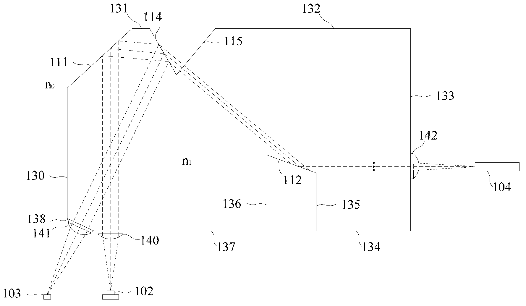
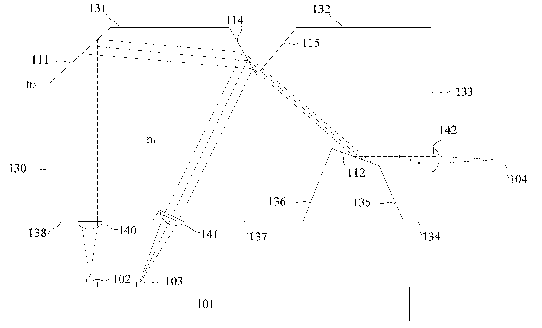
[0058] figure 1 It is a schematic structural diagram of a lens optical device according to an embodiment of the present invention. see figure 1 , the lens optics device includes: a polyhedron unit 110, a collimator lens 140, a first focusing lens 141 and a second focusing lens 142, wherein the polyhedron unit 110 is integrally molded with a polymer material, and at least includes: a first total internal reflection interface 111 , the catadioptric interface 114, the second total int...


PUM


Abstract

The invention discloses lens optical equipment and a light path transmission method based on the lens optical equipment. A collimating lens fixed on a collimating interface receives a laser beam and carries out collimating processing, the laser beam is transmitted to a first total internal reflection interface to be subjected to total internal reflection to form a total internal reflection light beam, the light beam is transmitted to a refraction and reflection interface to be subjected to reflection and refraction, a reflection light beam is transmitted to a first focusing interface perpendicular to the reflection light beam transmission direction, a first focusing lens fixed on the first focusing interface carries out focusing on the transmitted reflection light beam, the light beam is transmitted to a light detector to be detected; a refraction light beam is transmitted to a refraction adjusting interface perpendicular to the refraction light beam transmission direction to be subjected to transmission, the light beam is transmitted to a second total internal reflection interface to be subjected to total internal reflection, the light beam is transmitted to a second focusing interface; a second focusing lens fixed on the second focusing interface carries out focusing on the transmitted reflection light beam, and the light beam is transmitted to optical fibers. According to the lens optical equipment and the light path transmission method based on the lens optical equipment, optical fiber transmission efficiency can be improved, and lens optical equipment cost is lowered.

Description

technical field [0001] The invention relates to light propagation technology, in particular to a lens optical device and an optical path propagation method based on the lens optical device. Background technique [0002] In optical equipment, lens optical equipment can realize the steering of the optical path and focus the optical path through the combination of modules, and is widely used in laser systems. In the laser system, the combined large-diameter focusing lens group module and wide-angle lens group module are usually used to steer and focus the optical path output by the laser, and set the detection optical path to collect the optical signal in the optical path to monitor the working status of the laser. Adjust the laser light intensity of the laser output optical path. However, in the existing semiconductor-based micro-manufacturing technology, each module is manufactured independently, and the manufacturing cost of the lens optical device with built-in steering, f...

Claims


Application Information

Patent Timeline
IPC IPC(8): G02B17/08G02B1/04G02B27/30
CPCG02B6/4214G02B6/32G02B6/4286G02B27/126
Inventor 王彬黄永亮
Owner HISENSE BROADBAND MULTIMEDIA TECH
Why Eureka
Try Eureka