Method for implementing power system stabilizer

A technology of power system and implementation method, applied in the direction of reducing/preventing power oscillation, etc., can solve the problems of inability to guarantee, limited phase shift range of PSS4B model, large gain change, etc., achieve good economic and social benefits, and ensure safety and stability of economy. Running, enhancing the effect of positive damping characteristics

Active Publication Date: 2013-09-11
NR ELECTRIC CO LTD +1
View PDF1 Cites 24 Cited by
  • Summary
  • Abstract
  • Description
  • Claims
  • Application Information

AI Technical Summary

Problems solved by technology

[0007] The low frequency oscillation is divided into three frequency bands: low frequency band, middle frequency band and high frequency band. The division of the three frequency bands is a good solution to the problem of large gain changes caused by a single function in the PSS2B model. In this way, it can ensure sufficient gain in the middle and low frequency bands, and also ensure that the effect of PSS4B in suppressing oscillation in the middle and low frequency bands is much more significant than that of PSS2B. However, the PSS4B model has a limited phase shift range and is only suitable for no Compensate the self-shunt excitation system with a small phase shift range, and cannot guarantee that the output torque of the PSS4B will always be consistent with the direction of the speed change (-30 degrees to 30 degrees) in the entire low-frequency oscillation range, resulting in a reduction in the suppression effect of the PSS4B in the high-frequency band
For the exciter excitation system with a large range of uncompensated phase shifts, PSS4B is not applicable, and sometimes it will cause divergent oscillations in the high frequency band, which will have a negative impact on the safe operation of the power system.

Method used


Image

  • Method for implementing power system stabilizer
  • Method for implementing power system stabilizer
  • Method for implementing power system stabilizer

Examples


Embodiment Construction

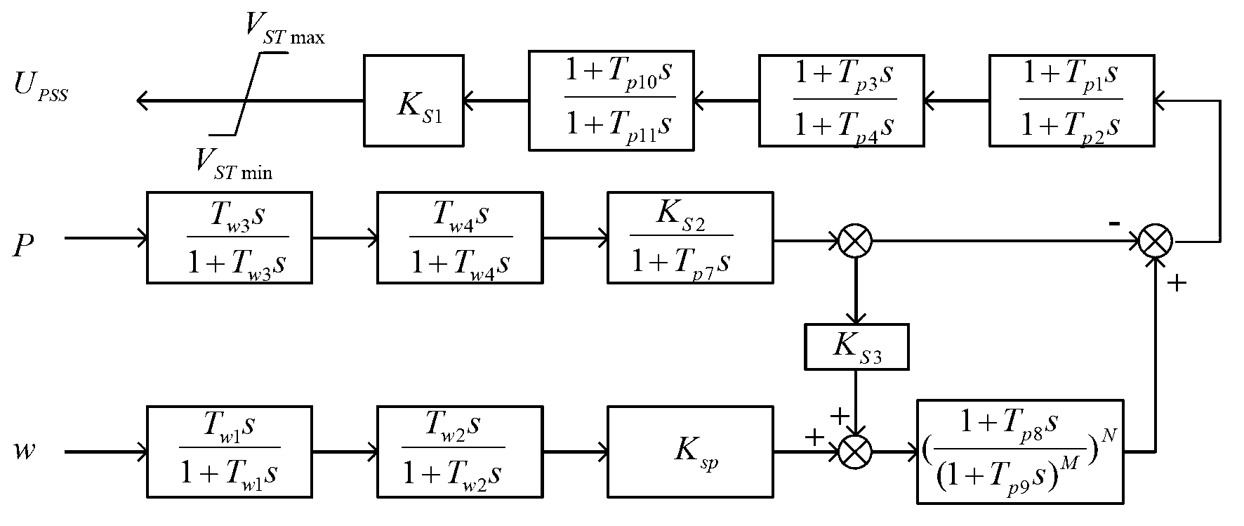
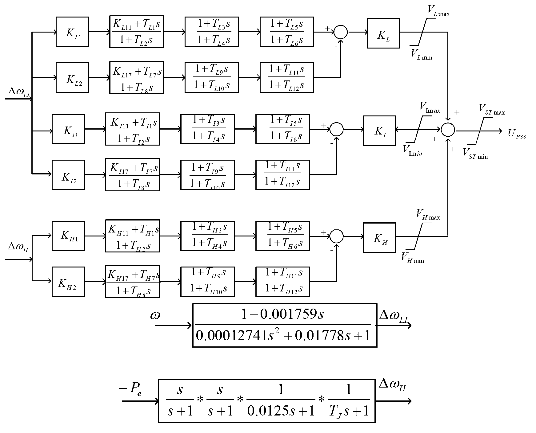
[0026] In order to further understand the technical content of the present invention, specific embodiments are given and described as follows in conjunction with the accompanying drawings.

[0027] According to the working principle of the power system stabilizer, the effect of the power system stabilizer on suppressing the low-frequency oscillation of the active power of the power system is mainly affected by two factors: one is the strength of the output signal of the power system stabilizer. Compared with the low-frequency oscillation of the same active power, the power system The stronger the output signal of the stabilizer, the more obvious its effect, and vice versa, the weaker the signal, the less obvious the effect, but the gain multiple of the power system stabilizer cannot exceed the critical gain, otherwise it will cause divergent oscillation and instability of the generator excitation control; One is the phase relationship between the output torque of the power syst...


PUM


Abstract

The invention discloses a method for implementing a power system stabilizer. The method includes steps of acquiring a rotation speed variable quantity via a blocking filter link according to the rotation speed and active power of a rotor of a power generator, and respectively acquiring low-band differential signals, medium-band differential signals and high-band differential signals via a differential filter; parallelly adding the low-band differential signals, the medium-band differential signals and the high-band differential signals together to acquire rotation speed variation comprehensive signals of the power generator; measuring phase-shift characteristics of the rotation speed variation comprehensive signals and the rotation speed and uncompensated phase-shift characteristics of an excitation control system of the power generator by a forced oscillation process, computing required phase-shift characteristics among the rotation speed variation comprehensive signals and the power system stabilizer, designing multi-order lead-lag link phase-shift parameters which are serially multiplied by one another, performing phase compensation to meet the required phase-shift characteristics; finally outputting signals of the power system stabilizer and superposing the signals of the power system stabilizer on a reference voltage of an excitation regulator of the power generator. The method has the advantage that active power low-frequency oscillation of the synchronous generator can be effectively suppressed.

Description

technical field [0001] The invention relates to the field of power system control, in particular to a method for realizing a power system stabilizer. Background technique [0002] The synchronous generator is connected to the power system through the transmission line for operation. The longer the transmission line, the weaker its damping, and the smaller the static limit power output of the line. When the active power generated by the synchronous generator exceeds the static limit power of the transmission line, the synchronous The active power generated by the generator will oscillate periodically. The oscillating frequency is related to the length of the transmission line, the capacity of the synchronous generator and the capacity connected to the grid. Generally, the frequency is in the range of 0.1Hz-2.0Hz, which is called low-frequency oscillation of active power. In addition, with the continuous expansion of the power grid, regional networking has become a trend. If t...

Claims


Application Information

Patent Timeline
Patent Type & Authority Applications(China)
IPC IPC(8): H02J3/24
Inventor 吴龙苏为民韩兵谢欢牟伟
Owner NR ELECTRIC CO LTD
Why Eureka
Try Eureka