

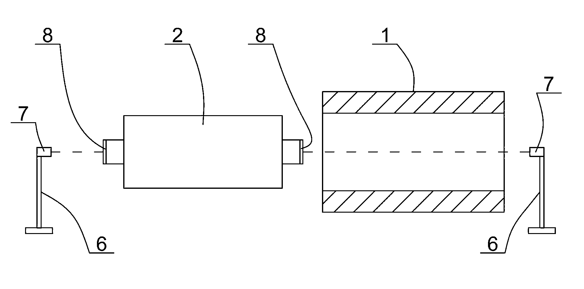
Centring method in process of mounting generator rotor in threading mode
A generator rotor and rotor technology, applied in the direction of adjusting/balancing rotors, measuring devices, using optical devices, etc., can solve the problems of difficulty in ensuring the coaxiality of the rotor and the stator, damage to the coil, insulation damage, etc., to achieve the centering state Intuitive and clear, reducing requirements and good directionality
- Summary
- Abstract
- Description
- Claims
- Application Information
AI Technical Summary
Problems solved by technology
Method used
Image

Examples
Embodiment Construction
[0047] The present invention will be further described below in conjunction with the accompanying drawings and specific embodiments.
[0048] A method for centering a generator rotor in assembly according to the present invention comprises the following steps:
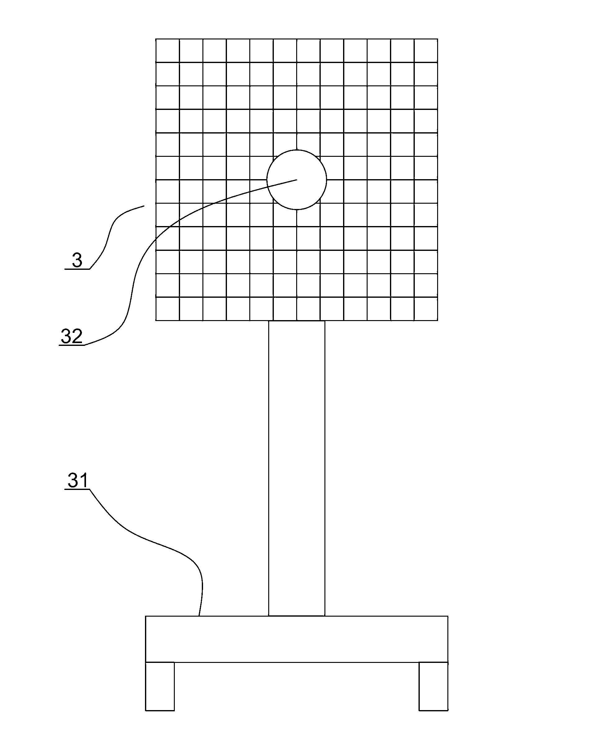
[0049] a) In the first step, vertically set a piece such as image 3 In the target plate 3 shown, there is a bull's-eye through hole 32 at the center of the target plate, and the bull's-eye through-hole is located on the center line of the stator.
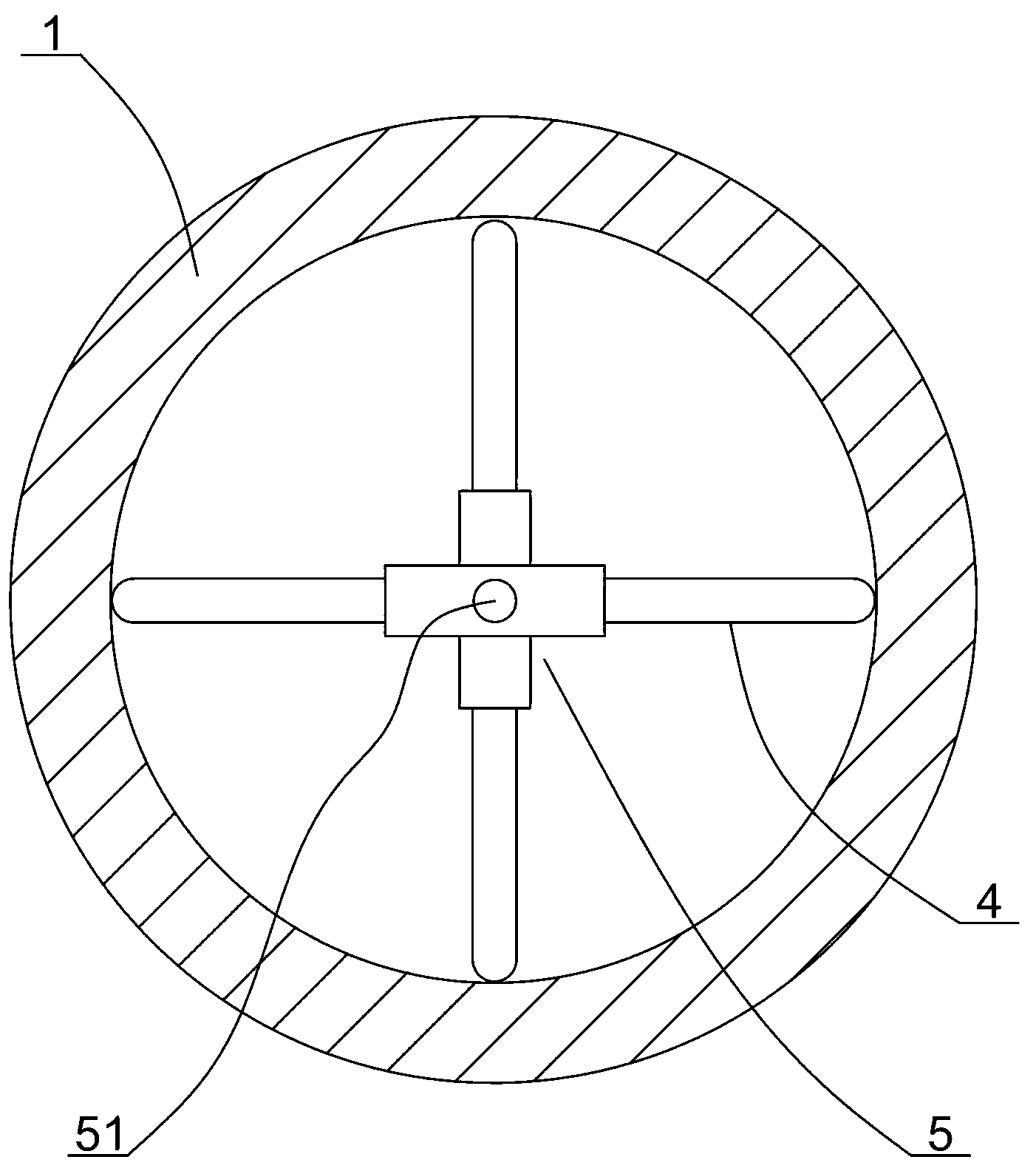
[0050] Specifically, we can use existing measurement tools to measure the inner diameter of the stator in the horizontal and vertical directions, and position the bull's-eye through hole at the center of the inner diameter of the two directions, so that the bull's-eye through-hole is basically guaranteed to be located on the center line of the stator . Of course, we can also use the following method to make the bull's-eye through hole located in the center of the end face...
PUM
 Abstract
Description
Claims
Application Information