Method for actuating a spark gap

A technology of spark gap and spark plug, applied in the field of spark gap, can solve problems such as difficult stable state

Active Publication Date: 2013-09-18
BORGWARNER BERU SYST
View PDF6 Cites 38 Cited by
  • Summary
  • Abstract
  • Description
  • Claims
  • Application Information

AI Technical Summary

Problems solved by technology

The disadvantage of this prior art is that it is very difficult to create a steady state at the spark plug fo...

Method used


Image

  • Method for actuating a spark gap
  • Method for actuating a spark gap
  • Method for actuating a spark gap

Examples


Embodiment Construction

[0118] In addition to spark plugs, the following description applies to spark gaps accordingly.

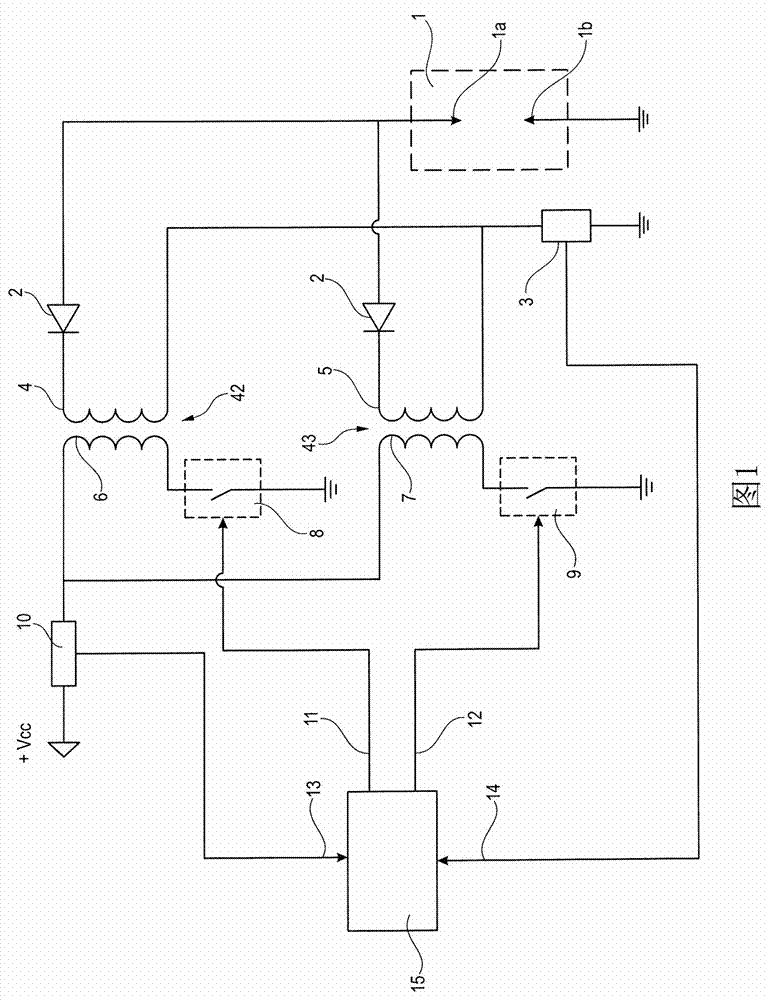
[0119] figure 1 The circuit arrangement illustrated in has a spark gap 1 , for example a spark plug, with a center electrode 1 a and a ground electrode 1 b. There are two ignition coils 42 and 43 to provide the necessary high voltage for the spark plug 1 . Ignition coil 42 has a primary winding 6 and a secondary winding 4 inductively coupled to primary winding 6 . The ignition coil 43 has a primary winding 7 and a secondary winding 5 which is inductively coupled to the primary winding 7 . For the sake of simplicity, the magnetic core coupling the primary winding 6 and the secondary winding 4 and the magnetic core coupling the primary winding 7 and the secondary winding 5 are not shown in the figure. The secondary winding 4 is located together with the spark plug 1 in the first secondary circuit. The secondary winding 5 is arranged together with the spark plug 1 in the second ...


PUM


Abstract

The invention discloses a method for actuating a spark plug (1) in an international combustion engine, wherein the spark plug (1) is assigned a first ignition coil (42) and second ignition coil (43). Triggered by a start signal (24), the primary winding (6) of the first ignition coil (42) is charged, and the primary winding (7) of the second ignition coil (43) is charged with a delay D, for which 0<=D, by supplying a direct current, wherein, whilst each primary winding (6, 7) , is charged, the respective secondary winding (4, 5) is blocked; the primary current supplied to the primary windings (6, 7) is measured; after a period T, the primary winding (6) of the first ignition coil (42) is discharged, and with the delay D the primary winding (7) of the second ignition coil (43) is discharged; the secondary current flowing through the spark plug (1) is measured; thereafter the primary windings (6, 7) of the first and second ignition coil (42, 43) start to be charged alternately when the secondary current falls below a threshold; the primary windings (6, 7) are discharged alternately when the primary current reaches an upper threshold; the above steps are repeated until the duration of discharge between two electrodes (1a, 1b) of the spark plug (1) reaches a predefined value Z.

Description

technical field [0001] The invention relates to a method according to the claims for driving a spark gap, in particular a spark plug, in an internal combustion engine. Background technique [0002] EP2325476A1 discloses a control unit for spark plugs in internal combustion engines which makes it possible to increase the duration of the ignition spark. For this purpose, it assigns two ignition coils to the spark plugs and operates them in such a way that they are shifted over time (controlled by the control device). The method begins with a start signal from the engine control unit for spark ignition, whereupon the two primary windings are connected to the vehicle battery or the vehicle's generator and charged. This happens as long as there is a start signal from the engine control unit. When the signal disappears, the two primary windings are discharged by opening a semiconductor switch arranged in the circuit of the primary windings. As a result, high voltages are induce...

Claims


Application Information

Patent Timeline
IPC IPC(8): F02P3/04
CPCF02P3/04F02P3/055F02P15/10F02P3/053F02P17/12F02P3/0456F02P3/0414F02P3/0442F02P3/0435F02P3/0407H01T13/44H01T15/00F02B75/18F02B2075/1808F02P3/045F02P3/05
Inventor 阮刚华D·基恩佐勒
Owner BORGWARNER BERU SYST
Why Eureka
Try Eureka