
A lake core sampling device for lake sediments with different water depths

A sampling device and sediment technology, applied in the direction of sampling devices, etc., can solve the problems of limited sampling range, low sampling success rate, disturbance, etc., and achieve the effect of improving sample integrity, improving sampling success rate, and increasing the depth of depression

Inactive Publication Date: 2016-05-25
BEIJING NORMAL UNIVERSITY
View PDF5 Cites 0 Cited by
  • Summary
  • Abstract
  • Description
  • Claims
  • Application Information

AI Technical Summary

Problems solved by technology

However, there are still some areas to be improved, mainly in: (1) There are some disturbances during sampling, and sometimes even destroy the sediment sequence; (2) The sampling method is single, and the comprehensive adaptability to different sampling environments is poor. In particular, it cannot meet the sampling work under different environmental conditions; (3) The length of sediment coring is short, and most of the collection of deep-water sediment lake cores can only reach a thickness of 40-50cm; (4) The success rate of sampling is not high And the cost is expensive, it is not conducive to disassembly and assembly, and it is difficult to repair after damage; (5) The sampling range is limited, and it cannot be applied to continuous sampling of deep-water lakes; (6) It cannot be applied to lake sediments of various textures, and for hard sediments For soft sediments, there will be a problem that it cannot be drilled, and for soft sediments, there will be a phenomenon of sample leakage

Method used


Image

  • A lake core sampling device for lake sediments with different water depths
  • A lake core sampling device for lake sediments with different water depths
  • A lake core sampling device for lake sediments with different water depths

Examples


Embodiment 1

[0058] Such as Figures 1 to 4 As shown, a lake core sampling device for lake sediments with different water depths, the lake core sampling device includes a handle rod 1, a drill rod 2 and a rotary core catcher 3 fixedly connected by welding in sequence from top to bottom;

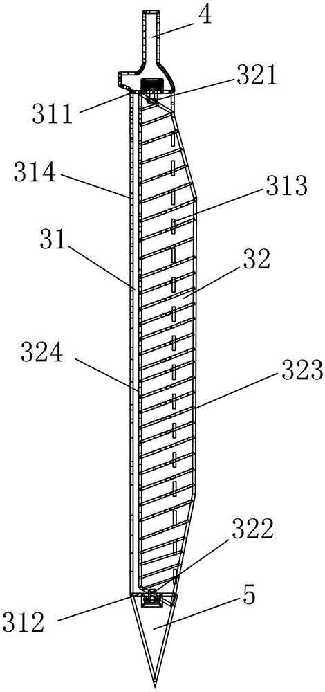
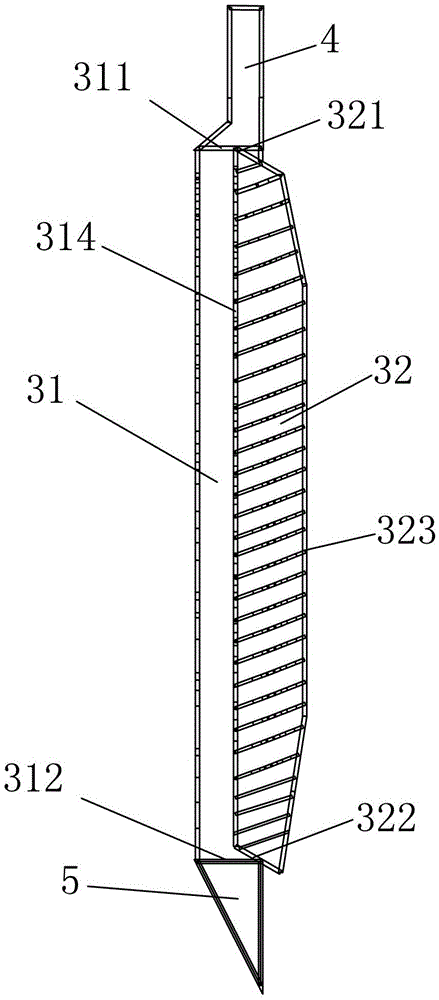
[0059] The rotary core catcher 3 includes a sample tube 31 and a rotary blade 32, the sample tube 31 body is a semicircular tank; the top 311 of the semicircular tank is provided with a Connecting rod 4, the outer surface of the bottom end 312 of the semicircular tank is fixed with a drill bit 5;

[0060] The two ends 321, 322 of the rotary blade 32 are respectively rotatably connected to the top end 311 and the bottom end 312 of the semicircular tank; one side 323 of the rotary blade 32 protrudes from the semicircular Outside the one side 313 of the arc-shaped wall of the tank body, the other side 324 of the rotary blade 32 is adjacent to the inner side wall 315 of the other side 314 of the arc-shaped w...

Embodiment 2

[0066] Such as Figures 5 to 8 As shown, the difference between this embodiment and Embodiment 1 is that: the handle rod 1 and the drill rod 2 are a sliding fit connection structure, that is, the drill rod 2 can slide in a matching manner in the handle rod 1; There is a first through hole 12, the drill rod 2 is provided with a first connecting hole 21, and the first through hole 12 and the first connecting hole 21 are fixed by bolts;

[0067] The purpose of this design is that the length of the lake core sampling device can be increased as required, which is beneficial to continuous depth lake core sampling.

[0068] The connecting rod 4 set on the top 311 of the semicircular tank body is sleeved in the drill rod 2, and the connecting rod 4 is provided with a second through hole 41, and the drill rod 2 is provided with a second through hole 41. The connection hole 22, the second through hole 41 and the second connection hole 22 are fixed by bolts.

[0069] Both connections a...

Embodiment 3

[0071] Such as Figure 9 , 10 As shown, the difference between this embodiment and Embodiment 1 is that: the drill pipe 2 is provided with a weight device, and the weight device includes a weight 6 sleeved on the drill pipe 2 and a weight fixed on the drill pipe 2. The bearing limit plate 61 on the rod 2 is used to bear the impact force of the weight 6 .

[0072] The lake core sampling device also includes a support frame 7, the top of the support frame 7 is provided with a pulley 71; the pulley 71 is provided with a steel wire rope 8, and one end 81 of the steel wire rope 8 is connected to the weight 6, The other end 82 of the wire rope 8 is a free end.

[0073] In this embodiment, for the structure of the lake core sampling device described in Embodiment 1, a heavy hammer device is added when sampling deep-water lakes. The heavy hammer 6 is a hollow concentric circle structure, which is sleeved on the drill pipe 2 and connected with one end 81 of a steel wire rope 8. The ...


PUM

PropertyMeasurementUnit
lengthaaaaaaaaaa

Abstract

The invention discloses a lacustrine core sampling device for sediments in lakes with different depths. The lacustrine core sampling device comprises a handle rod, a drilling rod and a rotary core capturing device which are sequentially fixedly connected from top to bottom, wherein the rotary core capturing device comprises a sample pipe and a rotary blade, a sample pipe body is a semicircular groove body, a connecting rod connected with the drilling rod is arranged at the top end of the semicircular groove body, a drill bit is fixedly arranged on the outer side surface of the bottom end of the semicircular groove body, and two ends of the rotary blade are respectively rotatably connected to the top end and the bottom end of the semicircular groove body. According to the lacustrine core sampling device, the defect of an existing mechanical sediment sampler is overcome, the sampling success rate and the sample integrity are increased, lacustrine cores of water bodies and marshes in different depths are sampled through the arrangement of prolongable drilling rod and a hammer, the dismantling link is greatly simplified, the time is effectively saved, and the demand on research is also met.

Description

technical field [0001] The invention relates to a bottom sediment sampler, in particular to a lake core sampling device for lake sediments with different water depths. Background technique [0002] The main purpose of environmental change science is to reconstruct the past climate, environment and ecological history of the earth through the study of natural records such as glaciers, deep-sea sediments, loess, permafrost, lake sediments, tree rings, and corals, so as to understand the evolution of the earth system. The past situation, the understanding of the changing laws of the earth's environment (including the changing process, changing range and changing rate) and its controlling factors provide the necessary background conditions and analogy models for predicting possible future global changes. [0003] The basic requirements for scientific drilling sampling (core) are: no disturbance, no deformation, no pollution; continuous and complete sampling, with a core sampling ...

Claims


Application Information

Patent Timeline
Patent Type & Authority Patents(China)
IPC IPC(8): G01N1/08
Inventor 马玉贞蒙红卫王维郭超
Owner BEIJING NORMAL UNIVERSITY
Learn More