Single-tube resonance type electronic ballast for gas discharge lamp

A technology for gas discharge lamps and electronic ballasts, which is applied in the direction of light sources, electric light sources, electrical components, etc., and can solve the problems of complex circuit structure of electronic ballasts, lack of feasibility of lamp dimming, and inconvenient switch tube control. , to achieve the effect of favorable design and production, remarkable energy saving effect and simple structure

Active Publication Date: 2013-09-18
佛山市信润电子科技有限公司
View PDF4 Cites 6 Cited by
  • Summary
  • Abstract
  • Description
  • Claims
  • Application Information

AI Technical Summary

Problems solved by technology

[0002] Gas discharge lamps are widely used due to their remarkable energy-saving effects. The existing electronic ballasts for gas discharge lamps use power conversion technology to generate high-frequency electric energy to drive the load of gas discharge lamps under the coordinated drive of several switching tubes. The main circuit includes multiple switching tubes and inductance coils, resulting in complex circuit structure, a lot of materials, and high cost. Because it is not convenient to control each switching tube separately, many existing electronic ballast technical solutions for gas discharge lamps do not have Feasibility of dimming the lamp, those electronic ballasts with dimming function are restricted by their own technical solutions, so the circuit structure is very complicated, the cost is high, and the price is expensive, especially for high-intensity gas discharge lamps with acoustic resonance problems , the circuit structure of its electronic ballast is very complicated, and the cost and price are very high

Method used


Image

  • Single-tube resonance type electronic ballast for gas discharge lamp
  • Single-tube resonance type electronic ballast for gas discharge lamp
  • Single-tube resonance type electronic ballast for gas discharge lamp

Examples


Embodiment Construction

[0027] The present invention will be described in further detail below in conjunction with the accompanying drawings.

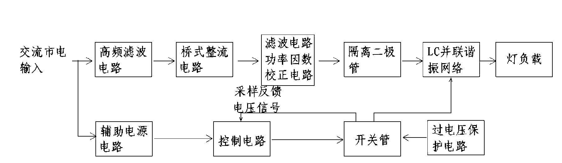
[0028] The gas discharge lamp electronic ballast is actually a power converter, which provides high-frequency alternating current power for the gas discharge lamp. The rectified AC mains power is converted into DC power, and then the DC power is converted into high-frequency AC power for the lamp load. It generally includes the main circuit, control circuit, necessary protection circuit and auxiliary power supply, etc., see figure 1 As shown, the general principle is: the AC mains is input into the bridge rectifier circuit, filter circuit or power factor correction circuit through the high-frequency filter circuit, and then outputs DC power, and the high-frequency inverter circuit behind the DC power input obtains tens of kilohertz (KHz ) high-frequency alternating current for gas discharge lamps; high-frequency filter circuits are used to filter out high-ord...


PUM


Abstract

The invention relates to a single-tube resonant type electronic ballast for a gas discharge lamp. An overall electric energy transmission scheme of AC-DC-AC (alternating current-direct current-alternating current) is used. An inverter circuit mainly comprises an isolating diode VD5, an LC resonance network formed by an inductor L2 and a capacitor C3 which are in parallel connection, a switch tube VT0 and a flyback diode VD0. A lamp load FZ is in serial connection with a capacitor C20 for ballasting. A soft switch working manner which is of zero voltage switching-on is used by the switch tube VT0. A pulse-width adjusting potentiometer R10 is used to adjust switching-on time of the switch tube VT0 so as to achieve the purpose of dimming. The switching-on time of the switch tube VT0 is modulated by low frequency, so that the acoustic resonance problem of the high-intensity gas discharge lamp is solved.

Description

technical field [0001] The invention provides a brand-new electronic ballast for single-tube resonant dimmable gas discharge lamp, which relates to the technical field of electric energy conversion electronic ballast for gas discharge lamp. A switch tube, by controlling and adjusting the conduction time of the switch tube of the main circuit, the purpose of dimming the lamp load and eliminating acoustic resonance is achieved. Background technique [0002] Gas discharge lamps are widely used due to their remarkable energy-saving effects. The existing electronic ballasts for gas discharge lamps use power conversion technology to generate high-frequency electric energy to drive the load of gas discharge lamps under the coordinated drive of several switching tubes. The main circuit includes multiple switching tubes and inductance coils, resulting in complex circuit structure, a lot of materials, and high cost. Because it is not convenient to control each switching tube separatel...

Claims


Application Information

Patent Timeline
Patent Type & Authority Applications(China)
IPC IPC(8): H05B41/288
Inventor 肖国选
Owner 佛山市信润电子科技有限公司
Why Eureka
Try Eureka