Implant-type blood flowing pump with self-suspended shaft

A self-suspension and implantable technology, applied in the direction of suction devices, etc., can solve the problems of complex structure of the magnetic levitation control system, easy wear of bearings, easy formation of thrombus, etc., and achieve the effect of light weight, good reliability, and avoiding thrombus

Inactive Publication Date: 2013-09-25
SHANGHAI MICROPORT MEDICAL (GROUP) CO LTD
View PDF4 Cites 7 Cited by
  • Summary
  • Abstract
  • Description
  • Claims
  • Application Information

AI Technical Summary

Problems solved by technology

[0005] Therefore, the inventors of the present invention have found that the existing implantable magnetic levitation axial blood pumps on the market have bearings, which are easy to wear and...

Method used


Image

  • Implant-type blood flowing pump with self-suspended shaft
  • Implant-type blood flowing pump with self-suspended shaft
  • Implant-type blood flowing pump with self-suspended shaft

Examples


Embodiment Construction

[0026] In the following description, many technical details are proposed for the reader to better understand this application. However, those of ordinary skill in the art can understand that even without these technical details and various changes and modifications based on the following embodiments, the technical solutions required by the claims of this application can be implemented.

[0027] In order to make the objectives, technical solutions and advantages of the present invention clearer, the embodiments of the present invention will be further described in detail below in conjunction with the accompanying drawings.

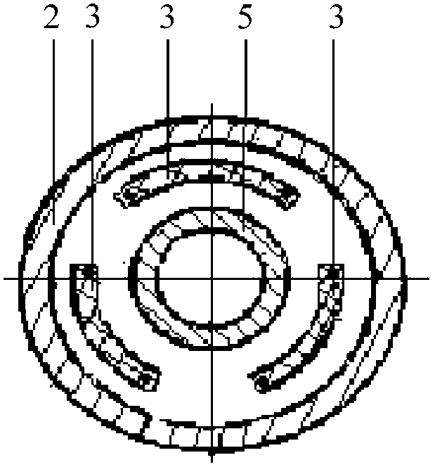
[0028] The first embodiment of the present invention relates to an implantable self-suspending axial blood pump. figure 1 It is a schematic diagram (cross-sectional view) of the implantable self-suspending axial blood pump.

[0029] Specifically, such as figure 1 As shown, the implantable self-suspending axial blood pump includes a stator and a rotor, wherein the ...


PUM


Abstract

The invention relates to the technical field of medical instruments and discloses an implant-type blood flowing pump with a self-suspended shaft. In the implant-type blood flowing pump, a rotor comprises a hollow cylindrical steel magnet (5) and built-in blades fixed in the steel magnet (5); the rotor is directly arranged in the middle of a stator; the stator is neither directly nor indirectly connected with the rotor through a bearing; the rotor automatically separated form the inner wall of the stator during rotating and is in a suspended state. As the bearing and a magnetic suspension control system are not adopted, the size of the implant-type blood flowing pump is smaller and the weight of the implant-type blood flowing pump is lighter, the implant-type blood flowing pump does not stop rotating when a mechanical failure occurs to the bearing, so that the reliability is higher, and the formation of thrombus in the position of the bearing is avoided. The implant-type blood flowing pump adopts a serial structure that the built-in blades (8) are in the front and the external blades (9) are in the rear; the tangent planes of the blades adopt the modes of the wings of a marine ducted propeller, so that the implant-type blood flowing pump can ensure that blood smoothly branches in and passes through main vessels and branch vessels.

Description

Technical field [0001] The present invention relates to the technical field of medical devices, in particular to an implantable ventricular assist device. Background technique [0002] Heart failure is the most common diagnosis of cardiovascular patients, and it is also the disease with the highest medical cost. The international community has regarded heart failure as an important issue to be solved in this century. Due to the lack of donors, about 30% of patients who are ready to receive heart transplants die of deteriorating heart function while waiting for a donor. [0003] The emergence and development of ventricular assist devices (Ventricular Assist Devices, referred to as "VAD") has given a new way to treat heart failure. Since 1981, the National Institutes of Health (National Institutes of Health, referred to as "NIH") Initiated the RFPs (a Request For Proposals, referred to as "Request for Proposals") program for the development of "implantable ventricular assist devices...

Claims


Application Information

Patent Timeline
IPC IPC(8): A61M1/12
Inventor 刘中民范慧敏周连第陈应生金如麟谭茀娃叶亮
Owner SHANGHAI MICROPORT MEDICAL (GROUP) CO LTD
Why Eureka
Try Eureka