Welding technology for microwave substrate

A substrate and microwave technology, applied in the electronic field, can solve problems such as poor stability and difficult process

Inactive Publication Date: 2013-09-25
DFINE TECH
View PDF10 Cites 11 Cited by
  • Summary
  • Abstract
  • Description
  • Claims
  • Application Information

AI Technical Summary

Problems solved by technology

[0007] The invention aims to solve the technical problems such as poor stability or very difficult process of traditional substrates directly bonded to the cavity, so as to

Method used


Image

  • Welding technology for microwave substrate

Examples


Embodiment Construction

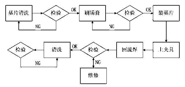
[0019] The detailed structure, application principle, function and effect of the invention, please refer to the attached figure 1 , Is explained by the following embodiments.

[0020] The present invention includes the following steps:

[0021] a) Use absolute ethanol or acetone to clean the microwave substrate, and then place the welding surface of the microwave substrate on the steel mesh;

[0022] b) Brush a layer of solder paste on the soldering surface of the above-mentioned microwave substrate. When painting, avoid the die bonding hole to prevent the solder from flowing into the hole after reflow soldering;

[0023] c) Put the microwave substrate coated with solder paste into the cavity of the product to be soldered, and press the microwave substrate with the press block, and then use the clamp to fix the press block and the microwave substrate;

[0024] d) Set the temperature curve of the reflow oven according to the size and thickness of the specific product. After the oven tem...


PUM


Abstract

The invention discloses a welding technology for a microwave substrate, relates to the electronic technical field and aims at solving the technical problems of poor stability, high technological difficulty and the like caused by the fact that substrates are bonded on cavities directly traditionally. The welding technology comprises the steps of a) cleaning the microwave substrate, and placing the microwave substrate on a steel mesh with the welding surface upward; b) coating a layer of solder paste on the welding surface of the microwave substrate, and avoiding a tube core bonding hole during coating; c) putting the solder paste coated microwave substrate in a product cavity, compressing the microwave substrate through a compression block and fixing the compression block and the microwave substrate with a clamp; and d) putting the product in a reflow oven for welding, taking down the clamp after welding, checking the welding quality, and cleaning the microwave substrate.

Description

Technical field [0001] The invention relates to the field of electronic technology, in particular to a microwave substrate welding process applied to microwave communication, satellite communication and radar. Background technique [0002] At present, with the continuous development of microwave technology, the frequency of microwave products is getting higher and higher, and the volume is getting smaller and smaller. Many products must at least reach the Ku, K, and Ka bands and above. In order to avoid signal leakage and electromagnetic interference, and the product can work stably and reliably in harsh environments for a long time, good grounding and reliability of the printed board substrate are particularly important. At present, the most common welding method for printed board substrates is to use conductive glue and alloy sheets for welding, but conductive glue and alloy sheets generally need to be imported at present, so the procurement cycle is longer and the cost is high...

Claims


Application Information

Patent Timeline
IPC IPC(8): B23K1/008
Inventor 肖攀
Owner DFINE TECH
Why Eureka
Try Eureka