Vacuum assistance system detection method, vacuum assistance system detection system, electromobile and failure detection method

A vacuum boosting and detection method technology, which is applied in the direction of brake safety system, etc., can solve the problems of poor vacuuming effect, vacuum pump not working, and inability to vacuum the vacuum tank, etc., so as to prolong the service life, ensure safe driving, and improve reliability Effect

Active Publication Date: 2013-09-25
奇瑞新能源汽车股份有限公司
View PDF7 Cites 40 Cited by
  • Summary
  • Abstract
  • Description
  • Claims
  • Application Information

AI Technical Summary

Problems solved by technology

[0004] However, the following problems still inevitably exist in practical applications: First, when the pressure sensor has a short-circuit or open circuit fault, the pressure sensor sends an unreliable detection result to the control unit, so that the control unit sends an unreliable detection result to the vacuum pump with reference to the unreliable detection result. The wrong control signal is sent out, causing the vacuum pump to work or not to work all the time; second, when the vacuum pump fails, the vacuum pump cannot vacuum the vacuum tank, or the vacuum pumping effect is poor, and it cannot provide a vacuum source to the vacuum booster system , making it difficult to step on the brake pedal, which in turn makes it difficult to brake; third, when the vacuum booster system (especially the vacuum tank) has an air leakage failure, the vacuum pressure in the vacuum tank is not stepped on the brake plate. It will also quickly rise to the first preset value, so that the vacuum pump is always in working condition, which seriously affects the service life of the vacuum pump

Method used


Image

  • Vacuum assistance system detection method, vacuum assistance system detection system, electromobile and failure detection method
  • Vacuum assistance system detection method, vacuum assistance system detection system, electromobile and failure detection method
  • Vacuum assistance system detection method, vacuum assistance system detection system, electromobile and failure detection method

Examples


Embodiment Construction

[0049] In order for those skilled in the art to better understand the technical solution of the present invention, the vacuum booster system detection method and system, the electric vehicle fault detection method and the electric vehicle provided by the present invention will be described in detail below with reference to the accompanying drawings.

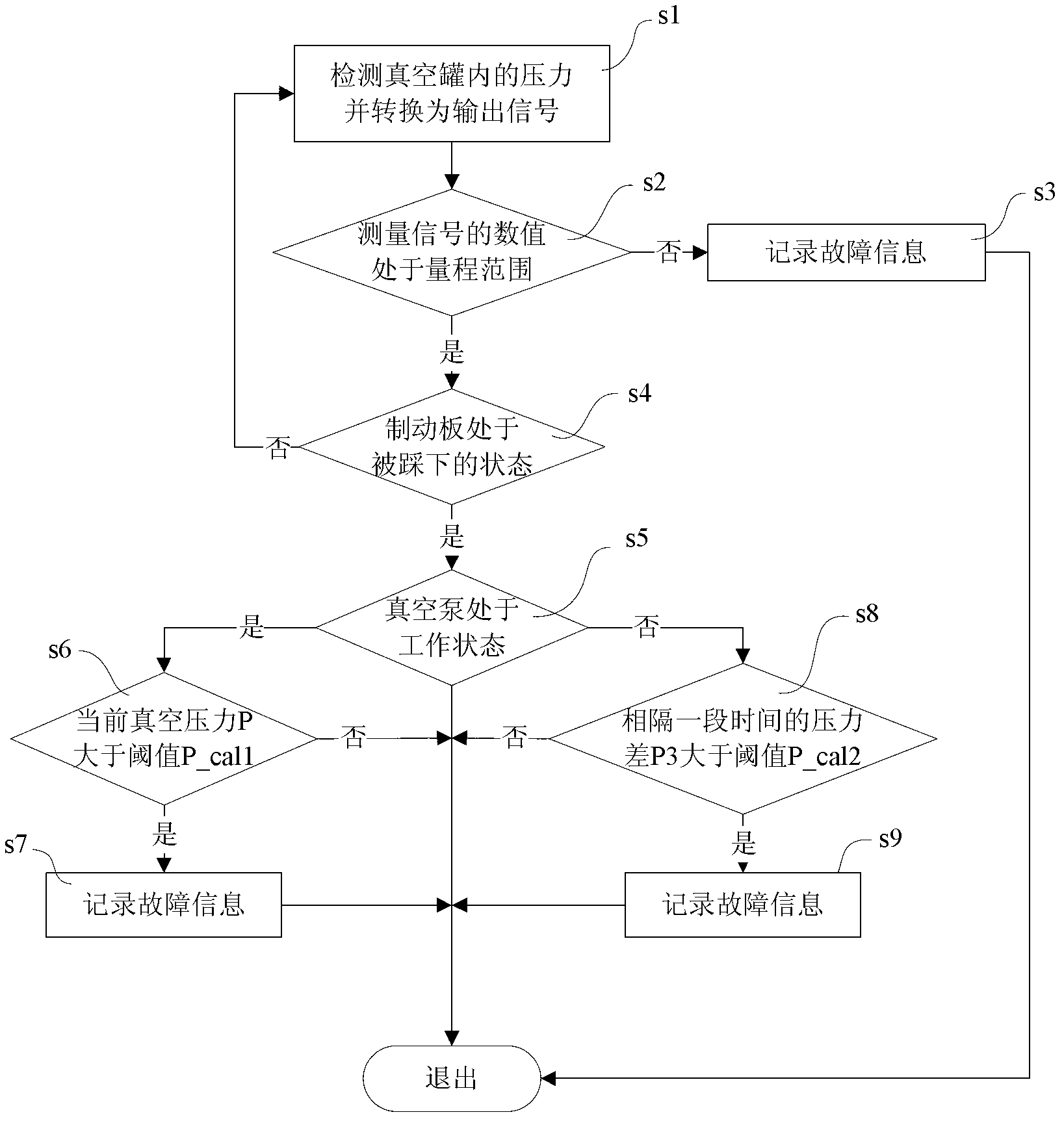
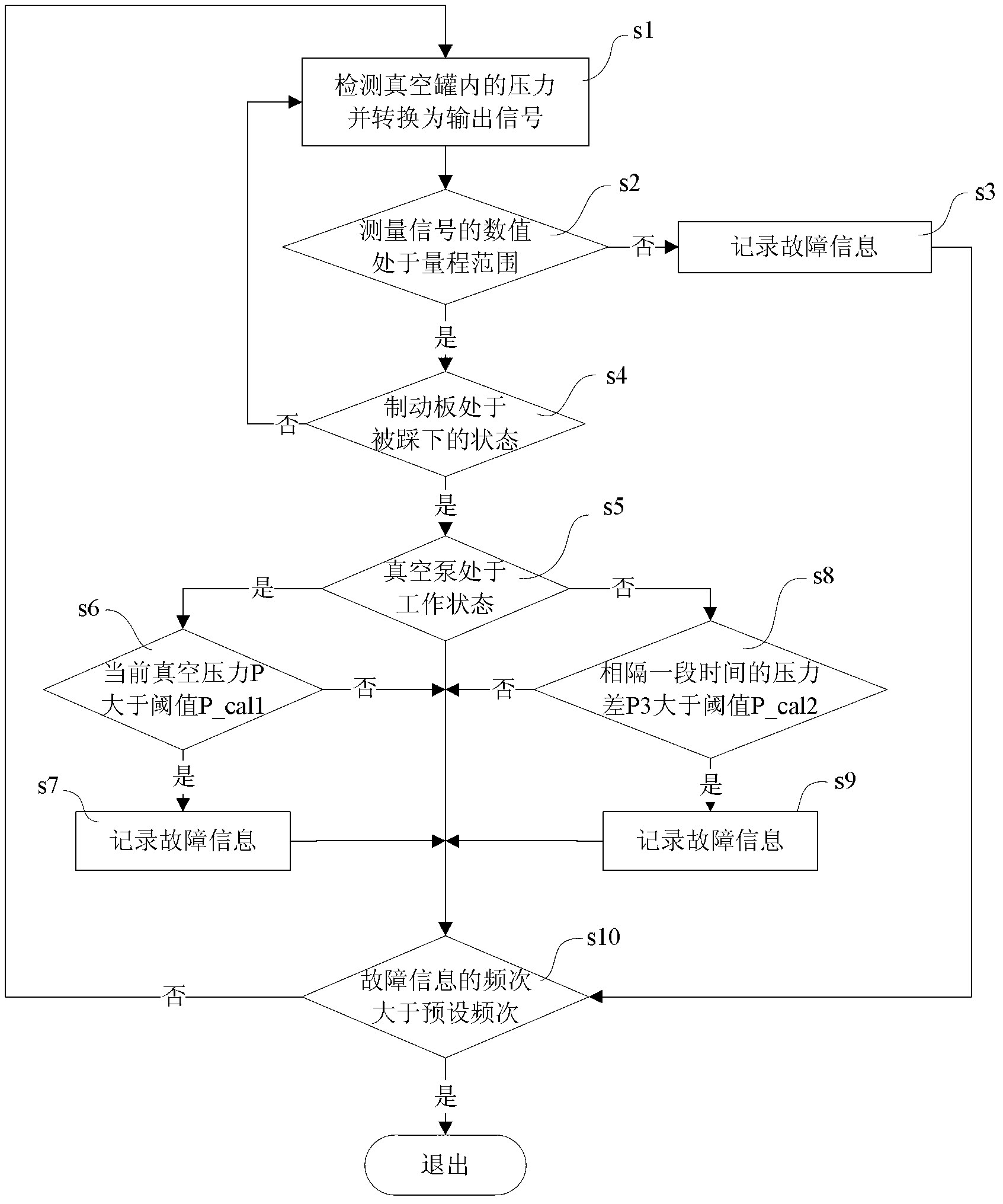
[0050] Such as figure 2 As shown, the vacuum boosting system detection method provided by Embodiment 1 of the present invention includes the following steps:

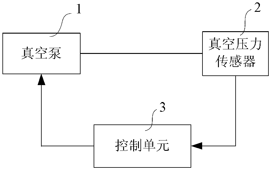
[0051] Step s1 is the detection step. Specifically, the pressure sensor detects the pressure in the vacuum tank, and outputs a measurement signal representing the pressure in the vacuum tank. Wherein, the measurement signal may be a voltage signal or a current signal.

[0052] Step s2 is the step of diagnosing the pressure sensor. Specifically, by judging whether the value of the measurement signal is within the range of the pressure sensor, it is judged whether the pr...


PUM


Abstract

The invention provides a vacuum assistance system detection method, a vacuum assistance system detection system, an electromobile and a failure detection method. The vacuum assistance system detection method includes the following steps: judging whether a pressure sensor fails or not; after the pressure sensor is guaranteed to be not in a failure, further diagnosing whether a vacuum pump is noneffective or not or whether a vacuum assistance system is in air leakage or not according to accurate measuring signals output by the pressure sensor. By the vacuum assistance system detection method, the vacuum assistance system can be detected accurately and comprehensively, and once the vacuum assistance system fails, failure positions can be quickly judged, so that reliability of the vacuum assistance system is effectively improved and driving safety of the electromobile is guaranteed.

Description

technical field [0001] The invention belongs to the technical field of electric vehicle control, and in particular relates to a detection method and system for a vacuum booster system, a fault detection method for an electric vehicle, and an electric vehicle. Background technique [0002] With the development of society and economy, the energy and environmental protection problems brought by traditional internal combustion engine vehicles have gradually attracted the attention of countries all over the world. Due to the increasing shortage of oil resources in the world and the environmental pollution caused by the emission of automobile exhaust, new energy vehicles have become the focus of research by various automobile manufacturers. Especially with the development of power batteries, hybrid vehicles and electric vehicles have become a relatively common development direction. Current electric vehicles generally use a vacuum braking system, including a vacuum pump, a vacuum...

Claims


Application Information

Patent Timeline
Patent Type & Authority Applications(China)
IPC IPC(8): B60T17/22
Inventor 孔令静陈信强王换换
Owner 奇瑞新能源汽车股份有限公司
Why Eureka
Try Eureka