

Condenser steam jet vacuum system
A vacuum system and condenser technology, applied in jet pumps, machines/engines, non-displacement pumps, etc., can solve problems such as maintenance cost reduction in unit efficiency, and achieve long-term stable operation, improved safety, and improved stability. Effect
Inactive Publication Date: 2013-09-25
上海赛迩福电力技术有限公司
View PDF5 Cites 3 Cited by
- Summary
- Abstract
- Description
- Claims
- Application Information
AI Technical Summary
Problems solved by technology
[0004] The purpose of the present invention is to overcome the deficiencies of the above-mentioned prior art, and provide a condenser steam injection vacuum system with simple structure, low maintenance cost, which can completely solve the problem of unit efficiency reduction caused by vacuum pump cavitation
Method used
View moreImage
Smart ImageViewing Examples

Examples
Embodiment 1
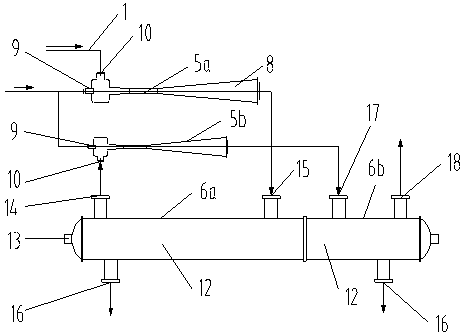
[0027] The vapor-gas mixture discharged from the condenser II6b enters the cold water separator after passing through the tubular heat exchanger.
Embodiment 2
[0029] The outlet pressure of the steam ejector II5b is 101.5Kpa, and there is no need to use moving parts and power-consuming parts.
Embodiment 3
[0031] The control system of the present invention can be controlled by a DCS system connected to the central control room of the power plant.
Login to View More PUM
 Abstract
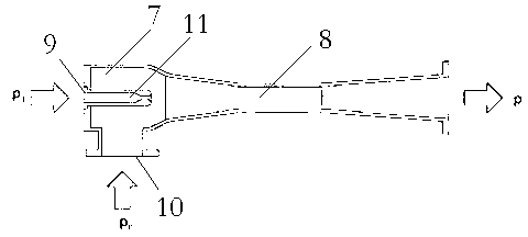
The invention discloses a condenser steam jet vacuum system which comprises a condenser pipeline connected with a condenser, a steam ejector set formed by at least a steam ejector I and a steam ejector II, and a condenser set formed by at least a condenser I and a condenser II. Power steam inlets of the steam ejector I and the steam ejector II are connected into power steam. Steam is used as media of the steam ejector I, and supersonic jet is produced through a power nozzle, so a head cavity is vaccumized to extract steam-gas mixtures in the condensers, the steam-gas mixtures exported from the condensers are mixed with the power steam and then are ejected into the condenser I through the steam ejector I to be processed in a condensed mode and finally are sucked in by the steam ejector II to be reprocessed. The condenser steam jet vacuum system is simple in structure and low in transformation cost, and can thoroughly solve the problem of unit efficiency reduction brought by vacuum pump cavitation.
Description
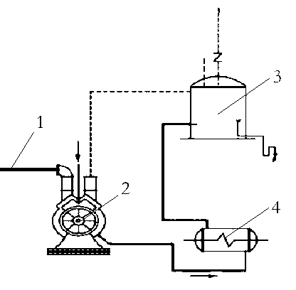
technical field [0001] The invention relates to an improvement to a condenser vacuum system, in particular to a condenser steam injection vacuum system. Background technique [0002] In a thermal power plant, a water ring vacuum pump is usually used to extract the non-condensable gas in the condenser to ensure the vacuum of the condenser. The specific plan is: see figure 1 , the condenser vacuum system in the prior art includes a condenser pipeline 1 connected to the condenser (not shown in the figure), and the condenser pipeline 1 is connected to the inlet end of the water ring vacuum pump 2 , the water ring vacuum pump 2, the steam-water separator 3 and the working fluid heat exchanger 4 are connected in pipelines to realize vacuum treatment. [0003] Its shortcoming is that the working fluid of the water ring vacuum pump is water, and its design temperature is generally 15°C, and the working fluid is cooled by circulating cooling water. However, the temperature of the ...
Claims
Login to View More Application Information
Patent Timeline
 Patent Type & AuthorityApplications(China)
IPC IPC(8): F04F5/22F04F5/52
Inventor程晋瑞
Owner上海赛迩福电力技术有限公司