Bionic air spring system

A technology of air springs and auxiliary air chambers, applied in springs, spring/shock absorbers, gas shock absorbers, etc., can solve the problems of long cycle, difficult quantitative adjustment, complex structure, etc., and achieve low equipment cost and wide application occasions , the effect of simple structure and process

Active Publication Date: 2013-09-25
SHANDONG UNIV
View PDF9 Cites 11 Cited by
  • Summary
  • Abstract
  • Description
  • Claims
  • Application Information

AI Technical Summary

Problems solved by technology

However, this document only gives the bionic mechanical model and the overall structural framework plan, and does not give the specific component structure, and the vibration isolation device given is composed of a platform, an air spring, a giant magnetostrictive actuator, a servo-type The active and semi-active vibration isolation system composed of sensors, height control valves, and control systems has a relatively complex structure, and the operation of actuators, sensors, etc. requires energy consumption
[0006] Although there are many kinds of air springs with various structures, most of the inventions are designed for specific load types (such as shock and vibration in a single direction), and it is difficult to transplant and apply to other loads, such as accompanying bending or torsion. The complex working conditions of equal coupling excitation, so the application is highl

Method used


Image

  • Bionic air spring system
  • Bionic air spring system
  • Bionic air spring system

Examples


Embodiment Construction

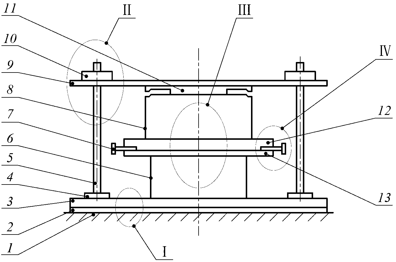
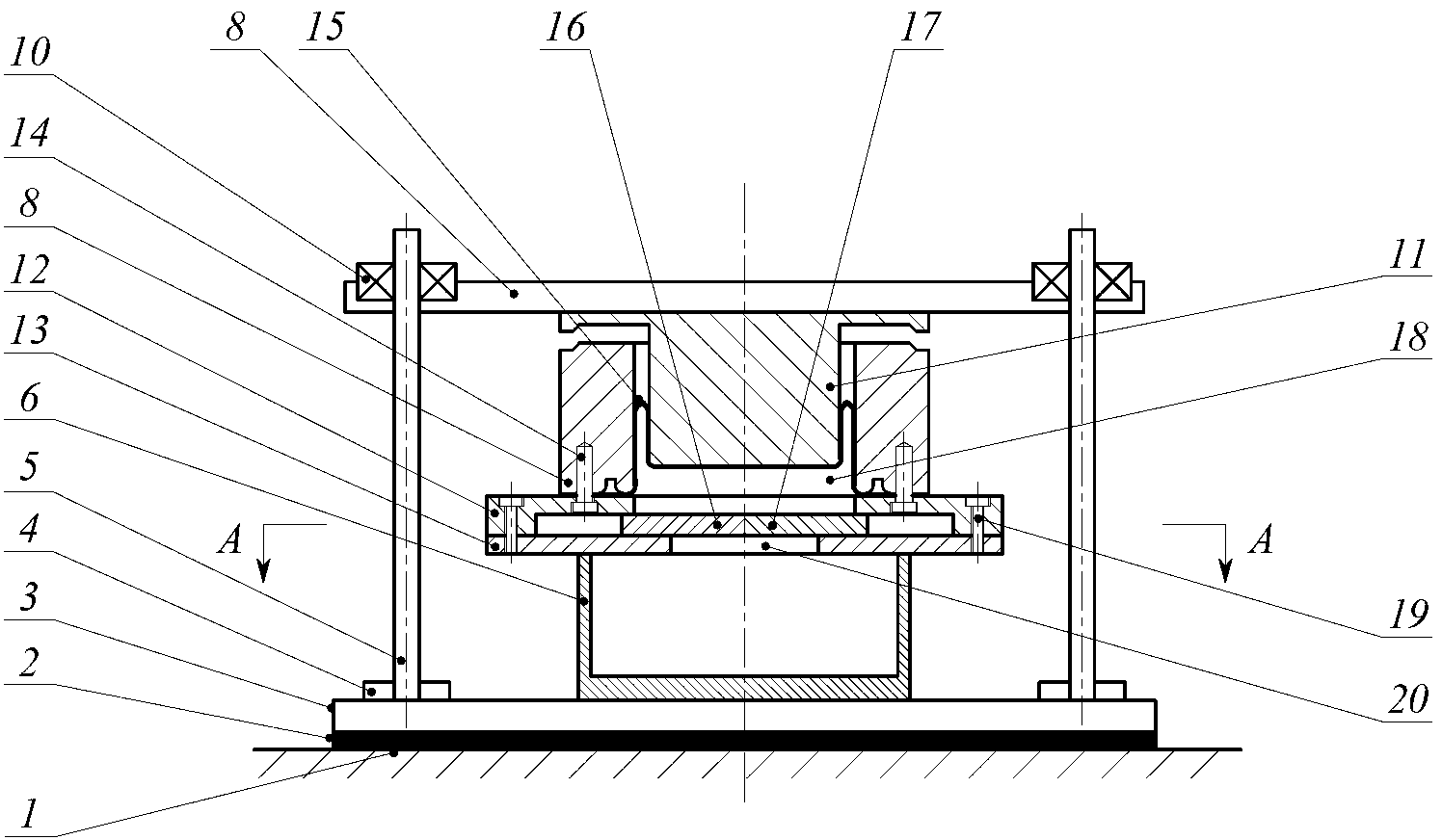
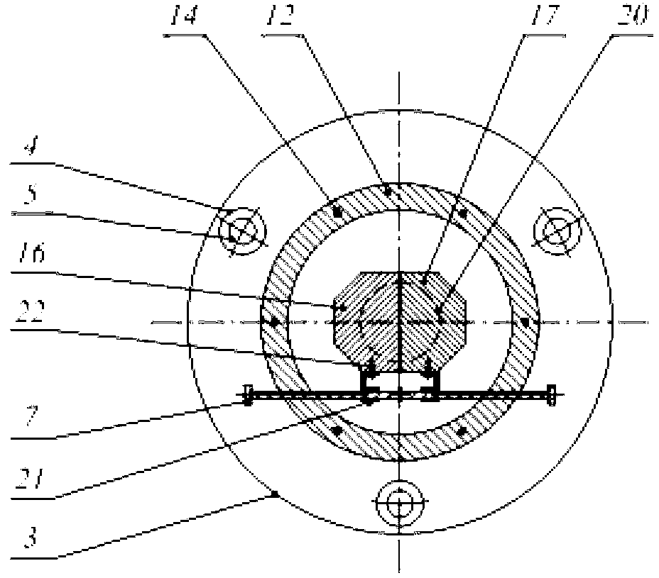
[0036] The present invention will be further described below in conjunction with the accompanying drawings and embodiments.

[0037] Generally, the ability to resist deformation of an object is defined as stiffness. The physical meaning of stiffness is the magnitude of the external force required by an object to produce unit deformation. Taking a spring-mass system with damping as an example, the general form of the differential equation of motion describing the vibration problem is In the formula. m, c, k are the mass, damping and stiffness coefficients of the system respectively, x(t), f(t) are the acceleration, velocity, displacement and external excitation of the system at time t, respectively, and t is time. When the spring produces a displacement x, the required force can be expressed as F=kx, where k is the stiffness. In the process of motion, the stiffness of the object remains unchanged, the stiffness is a constant value, and when the stiffness changes continu...


PUM


Abstract

The invention discloses a bionic air spring system which comprises a passive vibration reduction component, a variable-rigidity variable-damping component, an anti-torsion vibration component, an aperture regulating mechanism and a bearing platform. The passive vibration reduction component is mounted on an environmental foundation; the variable-rigidity variable-damping component is arranged on the upper portion of the passive vibration reduction component; the anti-torsion vibration component is disposed on the periphery of the variable-rigidity variable-damping component; the lower end of the anti-torsion vibration component is fixed into the passive vibration reduction component, the bearing platform is sleeved at the upper end of the anti-torsion vibration component, and the upper end of the variable-rigidity variable-damping component is in contact with the lower surface of the bearing platform. By regulating a lead-screw transmission mechanism, aperture openness of damping holes is regulated, flow rate and velocity of fluid between a main air chamber and an auxiliary chamber are changed, and the rigidity value and the damping value of the air spring system are quantitative and adjustable. Meanwhile, three aerostatic bearings are uniformly distributed along the axis of the bionic air spring system to form the anti-torsion vibration component to simulate the three-point support attitude of both claws and the tail of a woodpecker, so that engineering adaptability and vibration reduction efficiency of bionic air springs are improved.

Description

technical field [0001] The invention relates to the field of vibration control technology and bionic technology, in particular to a bionic air spring system. Background technique [0002] At present, vibration protection and shock isolation involve all aspects of social production and life. In recent years, the challenges faced by vibration reduction and anti-shock technology have become more severe. On the one hand, the excitation and coupling of various random factors under different working conditions make the dynamic environment of mechanical equipment extremely complex. On the other hand, precision and ultra-precision machining , Aerospace and other fields of equipment have higher requirements on the performance of vibration damping components. In addition, the improvement of the quality of life has made people more demanding on the ride comfort and ride comfort of transportation vehicles. Therefore, it is very necessary to design vibration damping devices with better...

Claims


Application Information

Patent Timeline
IPC IPC(8): F16F9/02F16F9/44F16F9/32
Inventor 唐委校吕宏卿宋清华牛庆良王玉松
Owner SHANDONG UNIV
Why Eureka
Try Eureka