Optimum control method of three operating devices
A technology for operating equipment and optimal control, applied in the direction of comprehensive factory control, comprehensive factory control, electrical program control, etc., can solve problems that affect the safe and stable operation of the system, the interlock logic is not too comprehensive, and reduce the degree of system automation, etc., to achieve Improve utilization efficiency and work efficiency, avoid chain errors, and reduce human resource consumption
- Summary
- Abstract
- Description
- Claims
- Application Information
AI Technical Summary
Problems solved by technology
Method used
Image
Examples
Embodiment 1
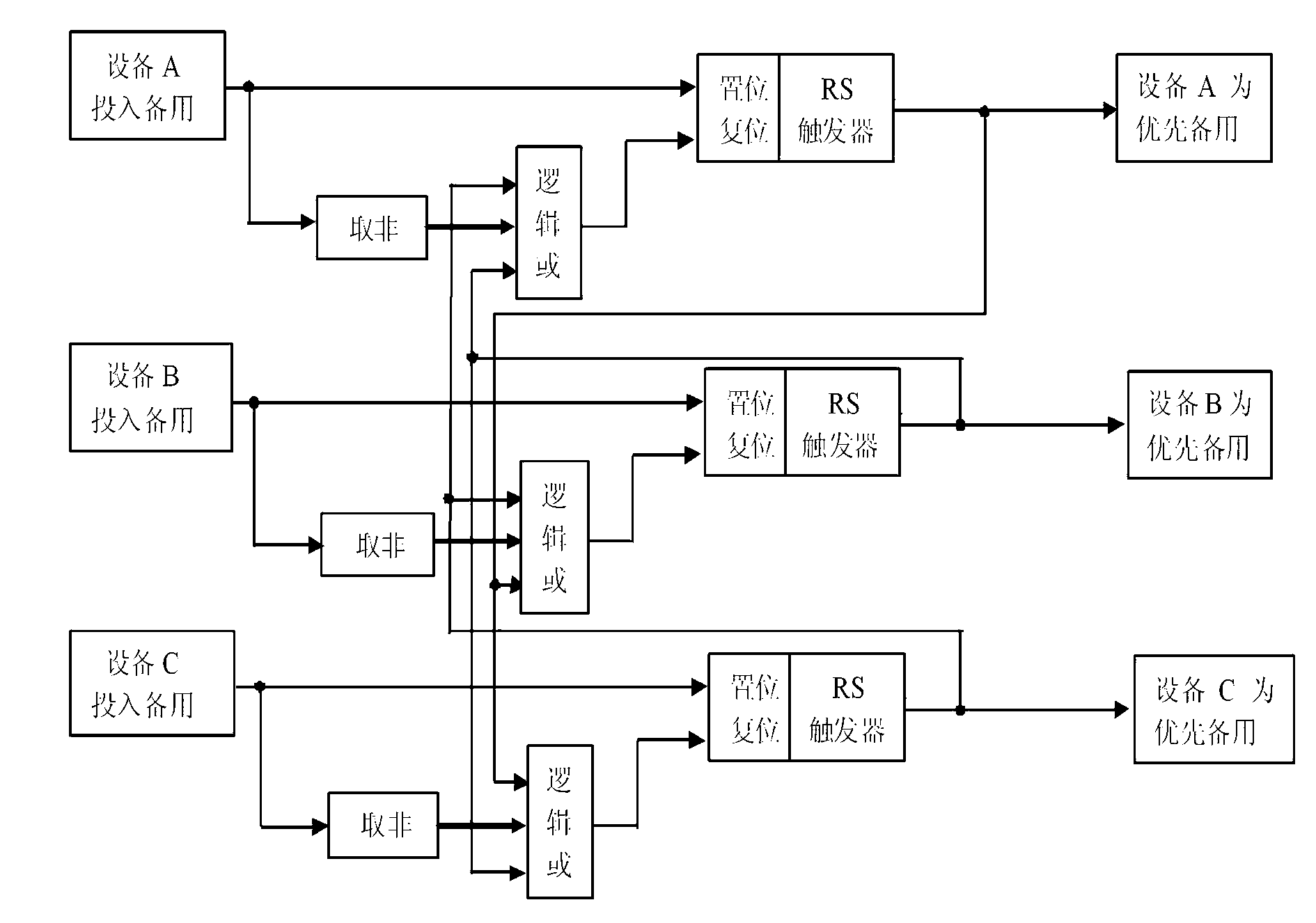
[0047] like figure 1 as shown, figure 1 It is a structural representation of the present invention. Which one of the three equipment is put into standby first, then which equipment is the priority standby equipment. If under the working condition of "one use and two standby", the equipment that is first chained to start is the priority standby equipment. If there is a problem with the priority standby equipment Or if the startup fails, another equipment put into standby will be started in chains.
Embodiment 2
[0049] like Figure 2a , Figure 2b , Figure 2c , Figure 2d as shown, Figure 2a-Figure 2d is an embodiment of the present invention. Figure 2a , Figure 2b , Figure 2c , Figure 2d What is realized is which equipment among the running equipment is put into priority for backup. and figure 1 The difference is that the selection is made according to the running time of the running equipment, that is, the selection of various time function blocks, which equipment has the shortest running time, and which equipment is the priority standby equipment. That is, the three devices can decide which one is the priority backup device according to the running time of the device. For example: the running time of device A is 100s, the running time of device B is 120s, and the running time of device C is 90s. Then when device A is running, the other two All equipments are put into standby, no matter which equipment is put into standby first, then the priority standby equipment is ...
Embodiment 3
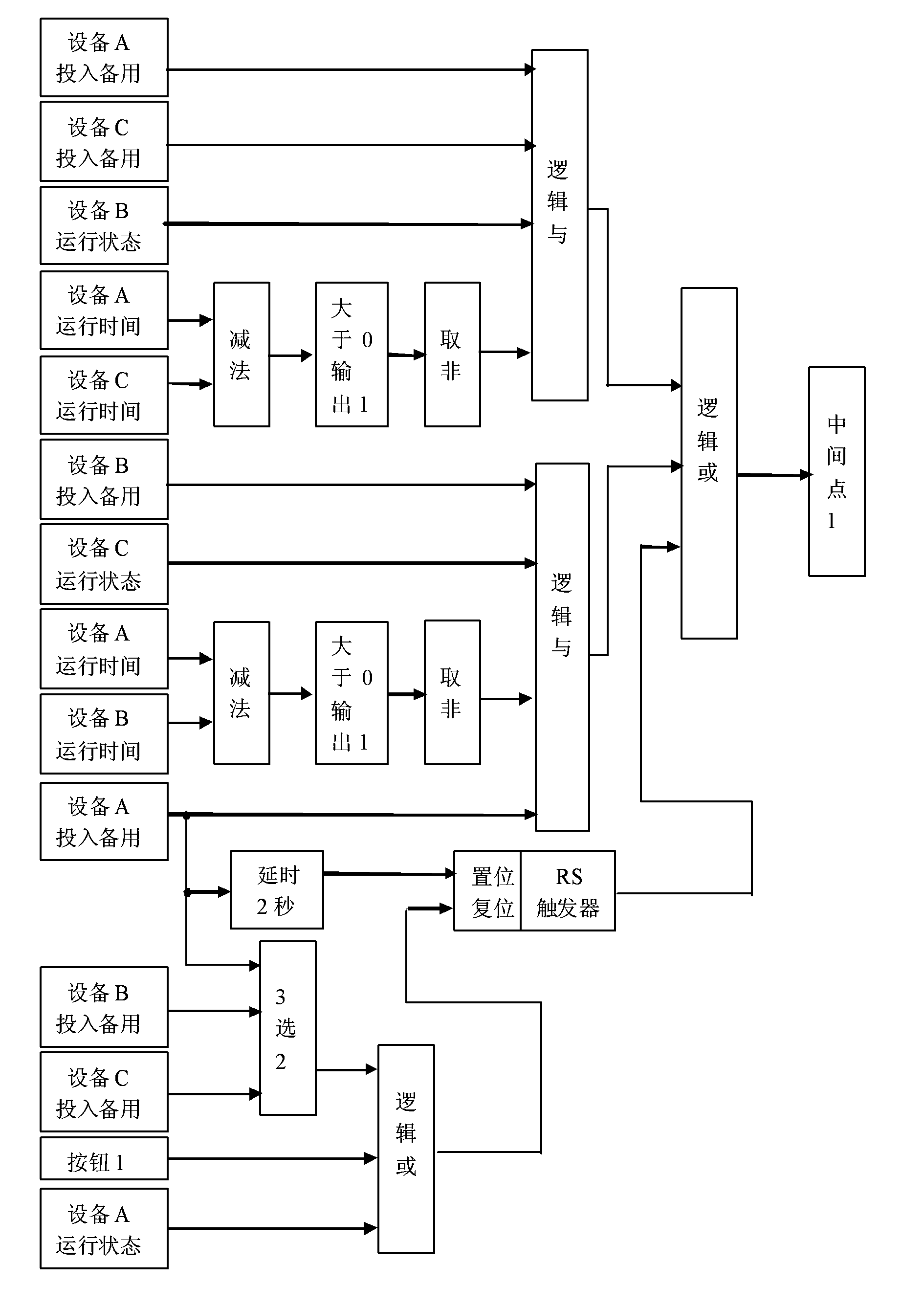
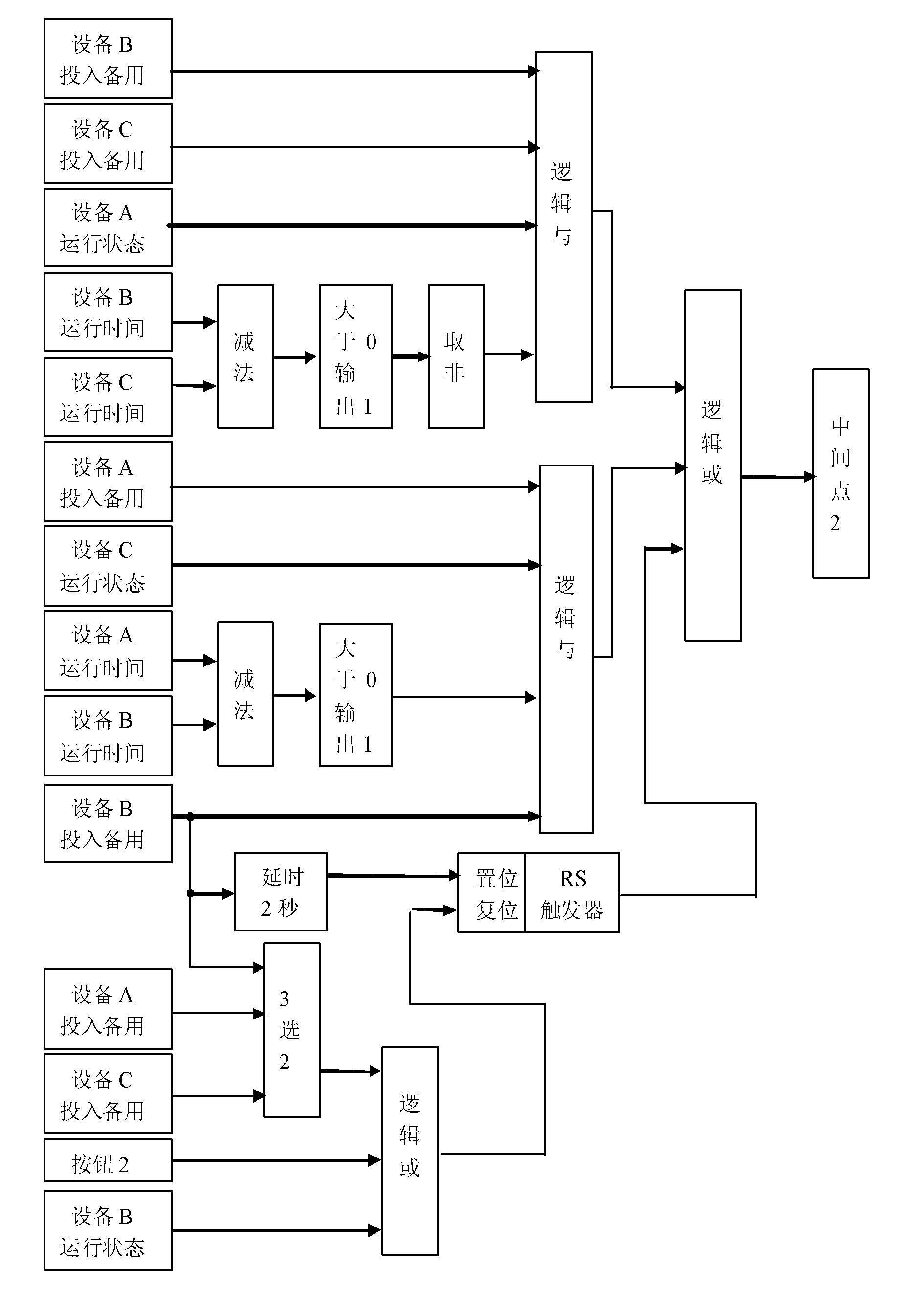
[0052] like Figure 3-Figure 5 as shown, image 3 It is the chain logic block diagram to realize the first running equipment; Figure 4 It is the chain logic block diagram to realize the second running equipment; Figure 5 It is the chain logic block diagram to realize the third running equipment. image 3 , Figure 4 , Figure 5 What is considered is that all DCS control systems only design the outlet header pressure, and the outlet of each operating equipment has no design pressure, the interlocking control thinking relationship between each equipment in each system. The outlet main pipe pressure of the DCS control system is redefined to the fixed value 1 according to the actual system operating parameters, and the delay time is also redefined to the delay function block 1 according to the interlocking time under the actual working condition of the system.
[0053] figure 1 and image 3 , Figure 4 , Figure 5 Combining, it can realize which device is put into prior...
PUM
 Abstract
Description
Claims
Application Information
 - R&D
- Intellectual Property
- Life Sciences
- Materials
- Tech Scout
- Unparalleled Data Quality
- Higher Quality Content
- 60% Fewer Hallucinations
Browse by: Latest US Patents, China's latest patents, Technical Efficacy Thesaurus, Application Domain, Technology Topic, Popular Technical Reports.
© 2025 PatSnap. All rights reserved.Legal|Privacy policy|Modern Slavery Act Transparency Statement|Sitemap|About US| Contact US: help@patsnap.com


