Transformer iron core and production method thereof
A production method and transformer technology, which is applied in the manufacture of inductors/transformers/magnets, transformer/inductor cores, electrical components, etc., can solve the problems of increasing production costs, increasing product inventory, and easy falling off of sound insulation blankets, etc., to reduce investment Cost, not easy to fall off, noise reduction effect
- Summary
- Abstract
- Description
- Claims
- Application Information
AI Technical Summary
Problems solved by technology
Method used
Image
Examples
Embodiment 1
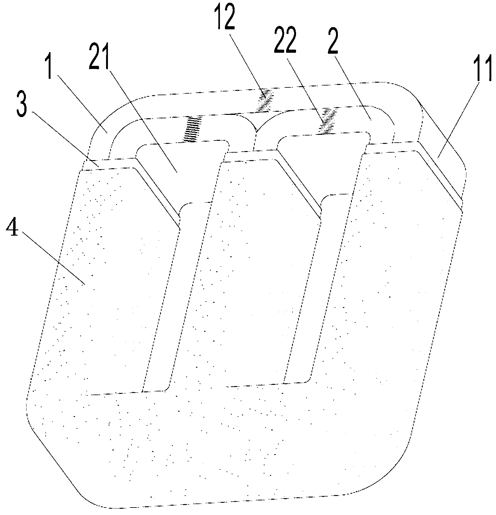
[0021] Embodiment 1 of a transformer core of the present invention: as figure 1 As shown, the transformer core includes a square ring-shaped outer core 1 and two square ring-shaped inner cores 2 nested in the outer core 1 and arranged side by side. Both the outer core and the inner core are amorphous alloy cores. The outer core 1 Including the outer iron core body and the outer core electrical steel belt 11 for protection wrapped around the body, the inner core 2 includes the inner core body and the inner core electrical steel belt 21 for protection wrapped around the body, the outer core 1 The upper end is provided with an outer iron core lap joint opening 12 for opening the iron core to fit the high and low voltage coils. The upper ends of the two inner iron cores 2 are provided with inner iron core lap joint openings 22. The outer iron core and the two inner iron cores form a three-column amorphous alloy core structure. The structure of the three-column amorphous alloy core...
Embodiment 2
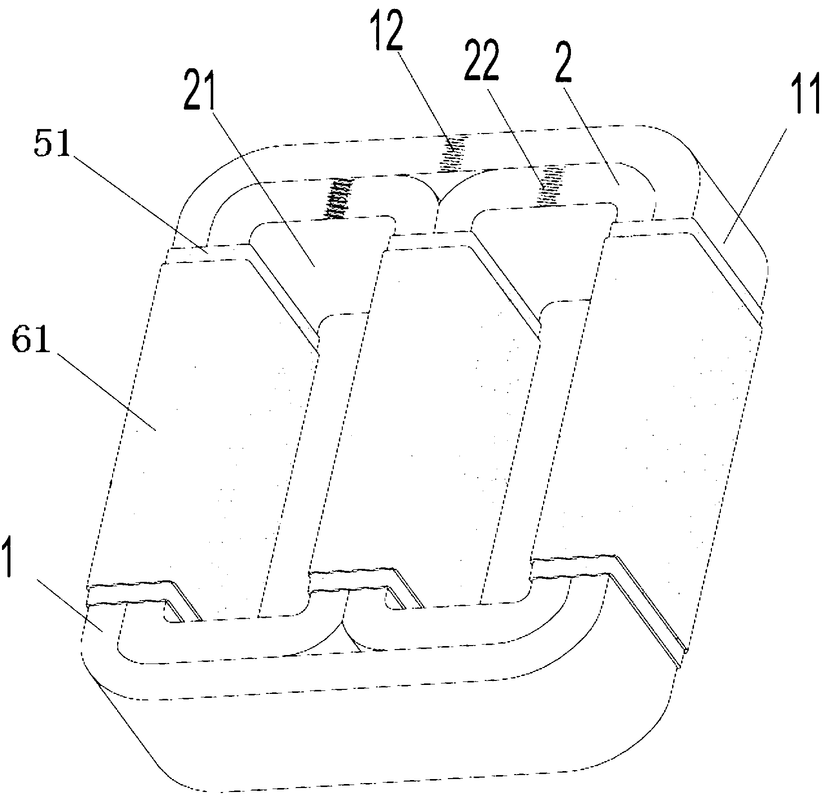
[0022] Embodiment 2 of a transformer core of the present invention: as figure 2 As shown, the difference from the above-mentioned embodiment is that this embodiment is only provided with two layers of columnar polyurethane foam layer sleeves on the outer circumferences of the first core column, the second core column and the third core column, and the polyurethane foam layer at the bottom of the single column 51 and the single-column composite polyurethane foam layer 61, each layer of polyurethane foam layer is wrapped with a fiberglass tape, and the remaining parts can be painted or brushed with epoxy resin for surface protection.
[0023] In each of the above-mentioned embodiments, it is a three-column amorphous alloy core structure. In other embodiments of the present invention, the iron core with a polyurethane foam layer on the surface can also be applied to an ordinary silicon steel dry-type core with a three-column or three-dimensional wound core structure. In the tran...
PUM
 Abstract
Description
Claims
Application Information
 - R&D
- Intellectual Property
- Life Sciences
- Materials
- Tech Scout
- Unparalleled Data Quality
- Higher Quality Content
- 60% Fewer Hallucinations
Browse by: Latest US Patents, China's latest patents, Technical Efficacy Thesaurus, Application Domain, Technology Topic, Popular Technical Reports.
© 2025 PatSnap. All rights reserved.Legal|Privacy policy|Modern Slavery Act Transparency Statement|Sitemap|About US| Contact US: help@patsnap.com


