Capacity coupling plasma reactor and control method thereof

A plasma reactor, capacitive coupling technology, applied in the direction of plasma, electrical components, etc., can solve the problem of not being able to use different hardware equipment and any processing technology in one design, achieve simple mechanism, achieve uniform distribution, and improve uniformity. Effect

Inactive Publication Date: 2013-09-25
ADVANCED MICRO FAB EQUIP INC CHINA
View PDF8 Cites 3 Cited by
  • Summary
  • Abstract
  • Description
  • Claims
  • Application Information

AI Technical Summary

Problems solved by technology

But no matter which method can only be optimized to a specific processing technology or hardware design, it is impossible to apply a design to different hardware devices and any processing technology

Method used


Image

  • Capacity coupling plasma reactor and control method thereof
  • Capacity coupling plasma reactor and control method thereof

Examples


Embodiment Construction

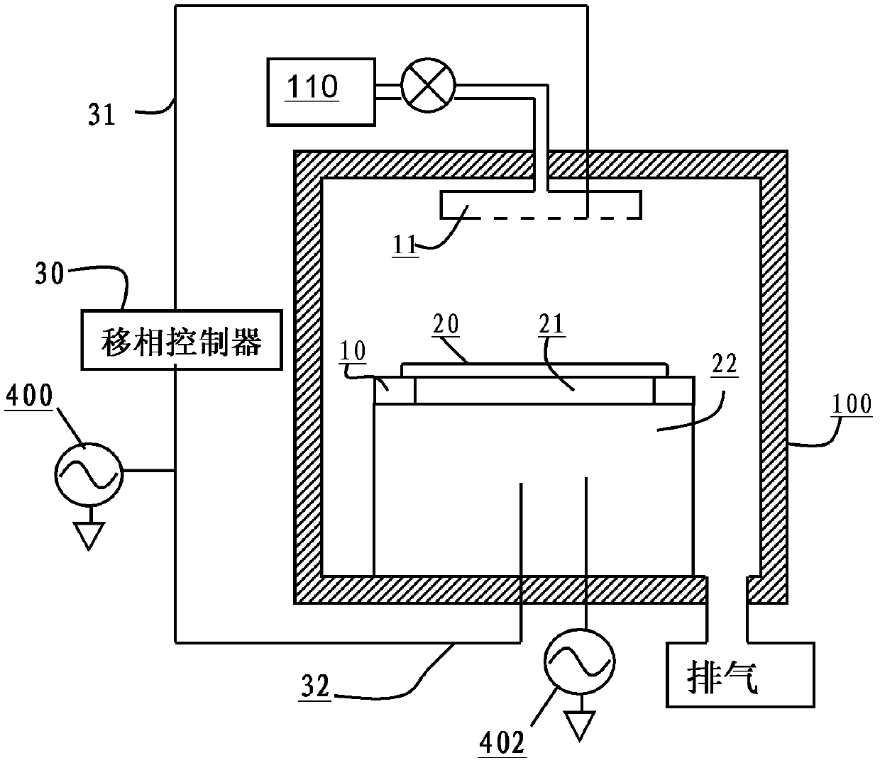
[0013] figure 1 A schematic longitudinal sectional view of a plasma processing apparatus according to the prior art is shown. Those skilled in the art understand that, in the prior art, a plasma processing device generally includes: a processing container 100 composed of a vacuum chamber whose interior is a closed space; The seat includes a lower electrode 22; and an upper electrode 11 arranged on the top of the base opposite to the base, the upper electrode is usually used as a gas nozzle at the same time, typically as a gas shower head, the gas shower head is connected to to process gas source 110.

[0014] The shape of the lower electrode 22 is adapted to the upper electrode 10; a substrate fixing device 21 for fixing the substrate 20 is arranged above the base, typically an electrostatic chuck. A substrate to be processed, such as a wafer, is placed above the substrate holding device 21 . Surrounding the substrate fixing device 21 and the substrate 20 also includes an e...


PUM


Abstract

The invention provides a capacity coupling plasma reactor which comprises a pedestal located at the bottom of the reactor. The pedestal comprises a bottom electrode inside and a top electrode. A high-frequency radio-frequency power supply, wherein the top electrode is opposite to the bottom electrode and located on the top of the reactor, the high-frequency radio-frequency power supply is connected to the bottom electrode and provides first high-frequency radio-frequency power, and the high-frequency radio-frequency power supply is connected to the top electrode and provides second high-frequency radio-frequency power. A low-frequency radio-frequency power supply is connected to the bottom electrode and provides low-frequency radio-frequency power. The capacity coupling plasma reactor is characterized by further comprising a phase shift controller connected between the high-frequency radio-frequency power supply and the top electrode or the bottom electrode. The phase shift controller enables phase difference between the first high-frequency radio-frequency power and the second high-frequency radio-frequency power to continuously change to stir plasma distributed on the surface of a substrate and achieve more even distribution of plasma concentration.

Description

technical field [0001] The present invention relates to semiconductor process equipment, especially a capacitively coupled plasma processing device for performing plasma processing on a substrate, and in particular relates to a radio frequency power applied between upper and lower electrodes of the capacitively coupled plasma processing device. Background technique [0002] In the manufacturing process of semiconductor devices, such as etching, deposition, oxidation, sputtering, etc., plasma is usually used to process substrates (semiconductor wafers, glass substrates, etc.). Generally, for a plasma processing device, it is used as a way to generate plasma. [0003] The plasma processing apparatus of the high-frequency discharge method includes a capacitively coupled plasma reactor. The capacitively coupled type reactor is generally provided with an upper electrode and a lower electrode, and these two electrodes are preferably arranged in parallel. In addition, usually, a s...

Claims


Application Information

Patent Timeline
Patent Type & Authority Applications(China)
IPC IPC(8): H05H1/46
Inventor 凯文·佩尔斯
Owner ADVANCED MICRO FAB EQUIP INC CHINA
Why Eureka
Try Eureka