
Actuator

A technology of actuators and driving parts, applied in the direction of brake types, automatic brakes, axial brakes, etc., can solve the problem of damaging the total efficiency of the actuator

Inactive Publication Date: 2013-09-25
MAGNA POWERTRAIN AG & CO KG
View PDF7 Cites 0 Cited by
  • Summary
  • Abstract
  • Description
  • Claims
  • Application Information

AI Technical Summary

Problems solved by technology

And this self-locking link will damage the overall efficiency of the actuator

Method used


Image

  • Actuator
  • Actuator
  • Actuator

Examples


Embodiment Construction

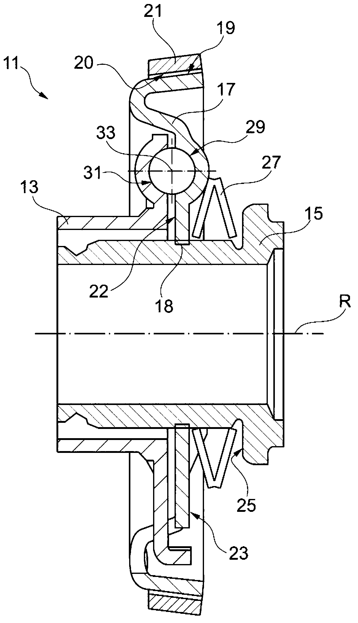
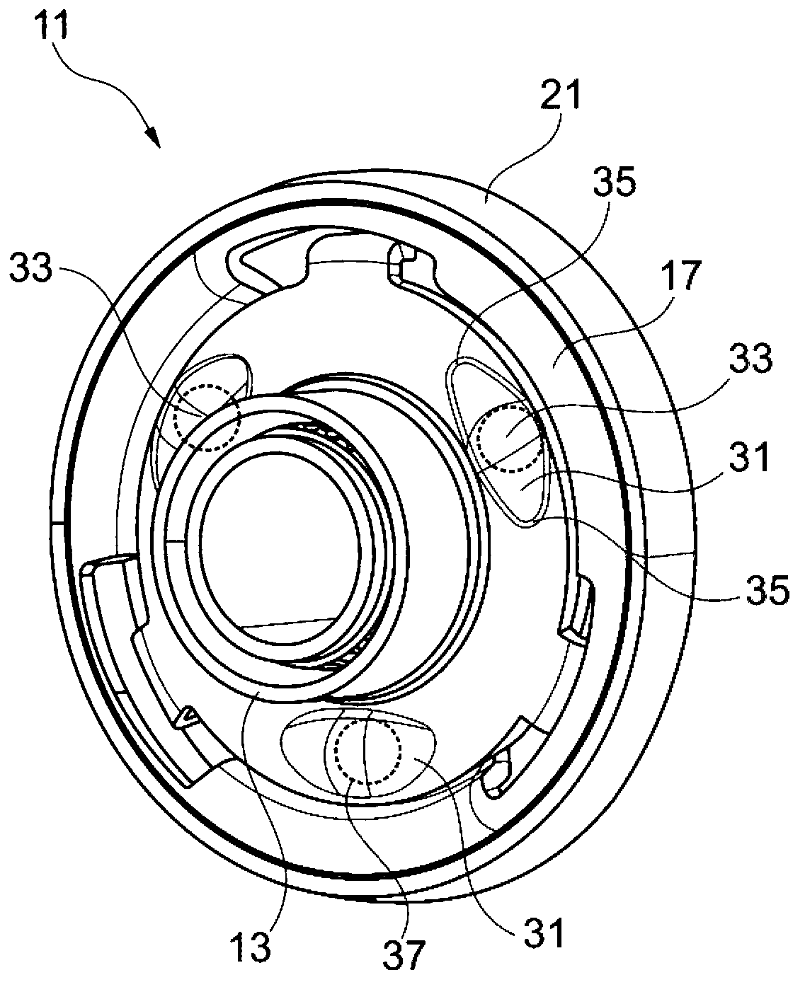
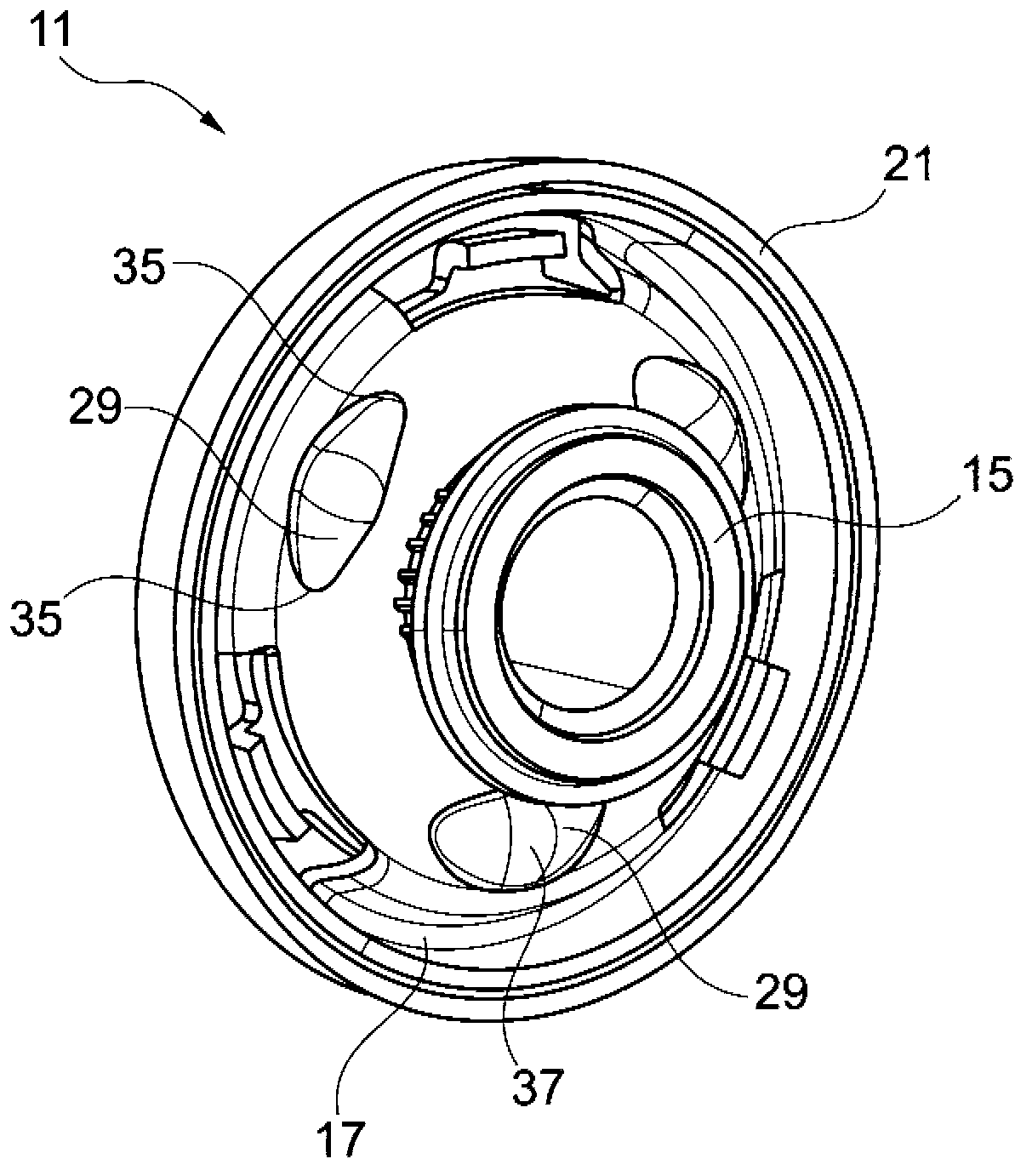
[0027] according to Figure 1 to Figure 3 The actuator 11 comprises a drive part 13 and a driven part 15 which are designed in the form of hollow shafts and are mounted rotatably about a common axis of rotation R in a housing (not shown) of the actuator 11 . The driving member 13 and the driven member 15 are axially fixed in the housing. The annular transmission part 17 is situated on the output part 15 and is mounted on the output part 15 in a non-rotatable, but axially displaceable manner by means of spline teeth 18 . Therefore, the transmission member 17 can move in the direction of the axis of rotation R figure 1 The resting position shown is the same as figure 1 Another right-hand working position not shown in the An outer cone surface 19 is designed on the outer peripheral surface of the transmission member 17. When the transmission member 17 is in a rest position, the outer cone surface 19 cooperates with the inner cone surface 20 of the brake ring 21 fixed on the ho...


PUM


Abstract

The invention relates to an actuator (11) comprising a drive element (13) which can be rotated about a rotational axis (R), an output element (15) which can be rotated about the rotational axis (R), and a coupling device via which the drive element (13) is coupled to the output element (15) forming torsional backlash. The coupling device comprises a transmission element (17) which is coupled to the output element (15) in a rotationally fixed manner and which can be moved between a rest position and an operating position relative to the output element (15). The transmission element (17) is rotationally secured in the rest position by a brake device (21) and can be rotated about the rotational axis (R) in the operating position, wherein the transmission element (17) is preloaded in the rest position by a spring device (27). The coupling device is designed such that, starting from the rest position of the transmission element (17), via an initial rotational movement of the drive element (13) using up the torsional backlash, the transmission element (17) can be moved against the spring preload into the operating position, and that, after the operating position is reached, the transmission element (17) can be driven to carry out a rotational movement by another rotational movement of the drive element (13) in order to thus also drive the output element (15) to carry out a rotational movement.

Description

technical field [0001] The invention relates to an actuator having a drive element rotatable about an axis of rotation, a driven element rotatable about the axis of rotation, and a coupling device by means of which the drive element forms a rotational gap. The lower is coupled with the follower. Background technique [0002] Rotary actuators are used in a large number of devices. Undesired rotation of the driven part is usually prevented when the actuator is in the inactive state. This is basically achieved by means of an additional actuator, for example an electromagnetic brake. However, this additional actuator involves an undesired increase in costs and weight. There may also be self-locking links in the drive chain of the actuator, such as trapezoidal threaded shafts. This self-locking link, in turn, impairs the overall efficiency of the actuator. Contents of the invention [0003] The technical problem underlying the invention is to provide an actuator of the afo...

Claims


Application Information

Patent Timeline
IPC IPC(8): F16D59/02F16D65/14
CPCF16D2065/024F16D55/02F16D67/00F16D2055/0058F16D2125/38F16D2127/001H02K7/003H02K7/102
Inventor E.雷格勒
Owner MAGNA POWERTRAIN AG & CO KG
Learn More