Intelligent oxygen inhaling measuring instrument

A measuring instrument and intelligent technology, applied in the direction of respirators, etc., can solve the problems of high cost, large error, and inability to be widely used in hospitals, and achieve the effect of reducing power consumption

Inactive Publication Date: 2013-10-02
杭州莱克思大医疗科技有限公司
View PDF5 Cites 4 Cited by
  • Summary
  • Abstract
  • Description
  • Claims
  • Application Information

AI Technical Summary

Problems solved by technology

At present, domestic hospitals generally use float flowmeters. The principle is to blow up the float in the tapered tube by the oxygen flow flowing through it, and visually measure the flow scale corresponding to the position of the float to calculate the flow rate. However, the defects of this type of product are large errors and inconvenient readings. , the data cannot be stored
[0003] In recent years, electronic flowmeters have also been produced in China by combining various gas flow sensors and single-chip microcomputers. The price of the flow sensor is very high. The unit price of the gas flow sensor alone ranges from hundreds to thousands of yuan, which causes the overall cost of the product to be too high, so it cannot be widely used in hospitals.

Method used


Image

  • Intelligent oxygen inhaling measuring instrument
  • Intelligent oxygen inhaling measuring instrument
  • Intelligent oxygen inhaling measuring instrument

Examples


Embodiment 1

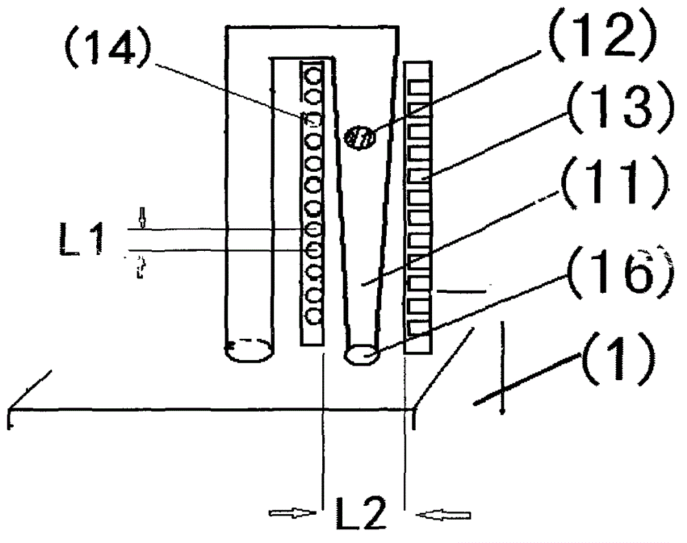
[0034] Embodiment 1: layout design of the optical scanning module. Main technical parameters: the height of the tapered tube (11) is 60mm, the light-emitting diode (13), photodiode / or phototransistor (14) are arranged facing each other, the flow calculation range is 1L-10L, and the error value does not exceed ±2.0%.

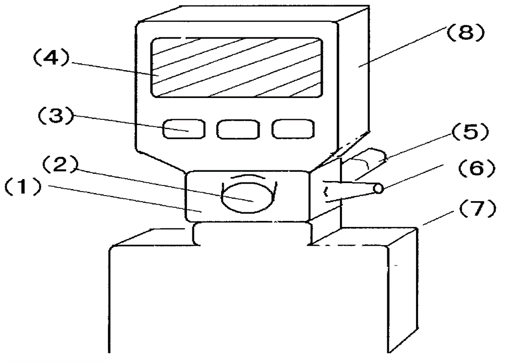
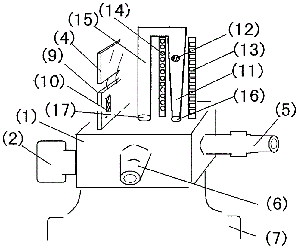
[0035] The present invention can pre-produce each component separately, and then produce it by module assembly, and the assembly of electronic components is a common technology, so Embodiment 1 of the present invention only describes the core technical part——the layout design of the optical scanning module in detail. The optical scanning module includes a base (1), a tapered tube (11), a float (12), a light emitting diode (13), a photodiode / or phototransistor (14), an integrated circuit (9) and the like.

[0036] 1. Use PE material to open a mold to produce a tapered tube (11) with a length of 60mm, an inner diameter of the upper end of 6.3mm, and an inner diamet...

Embodiment 2

[0041] Embodiment 2: Establishment of data model of "float position-corresponding flow" in the present invention

[0042] Taking the product prepared in the first embodiment of the present invention as an example, the working method of the present invention is further described:

[0043] 1. The height of the product taper tube (11) prepared in embodiment one is 60mm, and 30 pairs of light-emitting diodes (13), photodiodes / or phototransistors (14) light scanning points are installed on the periphery of the taper tube (11), that is, Said that the tapered tube (11) with the maximum flow calculation range of 1-10L and the effective movement range of the float (12) of 60mm is divided into 30 equal gratings on average, the scanning distance of each pair of gratings is 2mm, and the flow rate corresponding to each pair of gratings The scale is 0.2L, so the measurement error value does not exceed ±2.0%.

[0044] 2, get a set of standard flowmeter, precision grade 1, oxygen input inter...


PUM


Abstract

The invention relates to an intelligent oxygen inhaling measuring instrument, belongs to medical instruments and measuring devices, which are used for calculating flow quantity, oxygen inhaling time and expense during oxygen inhaling treatment, and has the advantages that the optical radiation scanning technology is adopted to determine the location of a floater, an integrated circuit and a singlechip are adopted to calculate and read the corresponding flow quantity, the degree of accuracy is high, the accuracy and the fairness of oxygen inhaling billing can be improved greatly, doctor-patient conflicts are reduced, meanwhile, the intelligent oxygen inhaling measuring instrument is more convenient and efficient, the workload of a nurse is reduced.

Description

Technical field [0001] The invention relates to an intelligent metering instrument for oxygen inhalation, which belongs to medical instruments and metering instruments used for calculating oxygen flow rate, oxygen inhalation time, oxygen inhalation cost, etc. during oxygen inhalation therapy. Background technique [0002] Oxygen inhalation is one of the most commonly used rescue or treatment methods in hospitals. The flow meter is one of the necessary equipment and measuring instruments for adjusting and observing the oxygen flow during oxygen inhalation. At present, domestic hospitals generally use float flowmeters. The principle is to blow up the float in the tapered tube by the oxygen flow flowing through it, and visually measure the flow scale corresponding to the position of the float to calculate the flow rate. However, the defects of this type of product are large errors and inconvenient readings. , the data cannot be stored. [0003] In recent years, electronic flo...

Claims


Application Information

Patent Timeline
Patent Type & Authority Applications(China)
IPC IPC(8): A61M16/00
Inventor 陈旭良刘晓曼
Owner 杭州莱克思大医疗科技有限公司
Why Eureka
Try Eureka