Machining method for worm gear tooth part

A processing method and worm gear technology, applied in the field of mechanical parts processing, can solve problems such as time-consuming, low production efficiency, and production difficulties, and achieve improved anti-gluing ability and wear resistance, good force bearing, and high bending strength. Effect

Active Publication Date: 2013-10-02
TIANJIN NO 1 MACHINE TOOL WORKS
View PDF6 Cites 5 Cited by
  • Summary
  • Abstract
  • Description
  • Claims
  • Application Information

AI Technical Summary

Problems solved by technology

However, due to various factors such as the manufacturing error of the hob, the center distance error during processing, and the temperature change, as well as the manufacturing error of the box, the installation error, and the force deformation and thermal deformation during work, it is inevitable that the contact area will The offset will affect the meshing transmission and service life of the worm gear pair, especially when matching the contact surface, it will take a lot of time and cause great difficulties in production
Using the above cutting tools and processing technology, the operation is time-consuming, laborious, and the production efficiency is low. Therefore, it is really a test for the operator to meet the accuracy requirements of the worm gear of the precision worm gear pair.

Method used


Image

  • Machining method for worm gear tooth part
  • Machining method for worm gear tooth part
  • Machining method for worm gear tooth part

Examples


Embodiment Construction

[0043] In order to further understand the invention content, characteristics and effects of this patent, the following examples are given, and detailed descriptions are as follows in conjunction with the accompanying drawings:

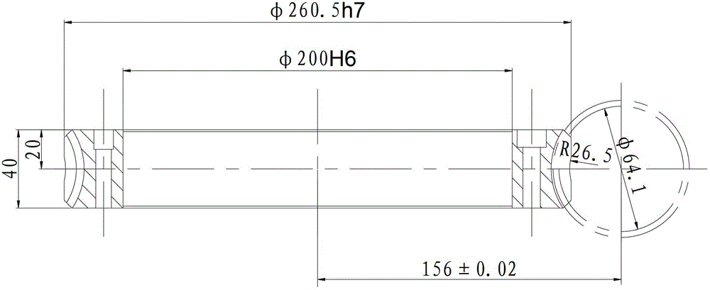
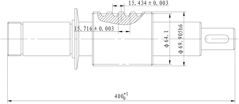
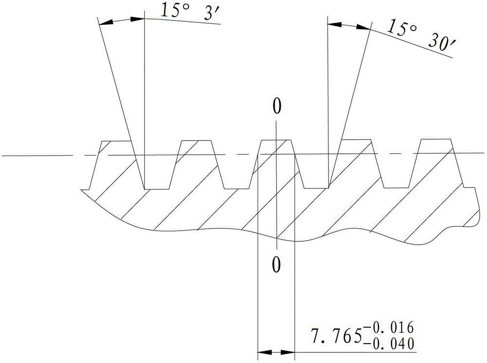
[0044] see Figure 1 to Figure 5 ,in figure 2 The arrow to the left indicates the thickening direction of the tooth thickness, the arrow to the right indicates the direction of thinning the tooth thickness, the vertical line at the root of the arrow to the left and the arrow to the right indicates the meshing center during assembly, Figure 5 The tooth shape in is the reference tooth shape for measurement.

[0045] figure 1 The parameters and technical requirements of the processed worm gear shown are: 1. Main parameters: center distance of worm gear pair: 156±0.02, axial modulus 4.958, number of teeth 50, nominal pitch circle helix angle 4°25′22″, helix direction Left, pressure angle 15°, meshing worm pitch circle diameter φ64.1, number of meshing...


PUM


Abstract

The invention relates to a machining method for a worm gear tooth part. The machining method comprises the steps that S1, arc machining is conducted on the worm gear tooth part; S2, the half angles of hobs and the center distance between the center of each hob and the center of a worm gear are calculated; S3, rough hobbing is conducted on the worm gear tooth part; S4, semi-finish hobbing is conducted on the worm gear tooth part; S5, finish hobbing is conducted on the worm gear tooth part; S6, grinding is conducted on the worm gear tooth part. The step S3, the step S4, the step S5 and the step S6 are all performed on a gear hobbing machine, and the same datum plane is utilized; the worm gear hubs used for gear hobbing conducted on the worm gear tooth part in the step S3, the step S4 and the step S5 are large-diameter worm gear hobs. The machining method has the advantages that a machined worm gear is high in accuracy and stable in transmission, contacting surfaces are easy to match, gear teeth are good in abrasion resistance, and bending strength is high.

Description

technical field [0001] The patent belongs to the technical field of mechanical parts processing, and in particular relates to a processing method of a worm gear tooth. Background technique [0002] The precision worm gear pair is a key part of the gear machine tool, and its quality will directly affect the precision of the gear machined by the machine tool. Gear machine tools such as gear milling machines and gear shaping machines have two pairs of worm gear pairs with this precision. It is one of the important key parts in gear machine tools, so the processing of worm gear teeth in precision worm gear pairs is very important. . [0003] At present, the processing of the precision worm gear pair worm gear is a single part processing, and the tools used are also ordinary worm gear hobs. The parameters of ordinary worm gear hobs, such as modulus, pressure angle, indexing circle diameter, number of heads, helix angle, etc., are completely consistent with the parameters of the...

Claims


Application Information

Patent Timeline
Patent Type & Authority Applications(China)
IPC IPC(8): B23F11/00
Inventor 李秀梅赵广珠
Owner TIANJIN NO 1 MACHINE TOOL WORKS
Why Eureka
Try Eureka