Eureka AIR delivers breakthrough ideas for toughest innovation challenges, trusted by R&D personnel around the world.

Automatic slag removal mechanism of welding torch of full-automatic CO2 (carbon dioxide) welding machine

A welding machine and fully automatic technology, applied in the field of welding torch, can solve the problems of inability to effectively protect the weld bead from oxidation, carbon dioxide cannot be ejected smoothly, and low work efficiency, and achieve simple structure, prevent welding torch from clogging, and high work efficiency Effect

Inactive Publication Date: 2013-10-02
嘉州包装机材(常熟)有限公司
View PDF6 Cites 5 Cited by
  • Summary
  • Abstract
  • Description
  • Claims
  • Application Information

AI Technical Summary

Problems solved by technology

The function of carbon dioxide is to isolate the air to ensure that the weld bead is not oxidized during the welding process to maintain the welding strength of the welded workpiece. However, due to the high temperature during welding, welding slag will be generated, and the welding slag will splash around and fly into the In the carbon dioxide protective cover, and stick to the inner wall of the protective cover, every few minutes after welding, it will be full of the protective cover (see Figure 4 ), so that carbon dioxide cannot be ejected smoothly, and thus cannot effectively protect the weld bead from being oxidized
In general manual welding or automatic welding, it is necessary to manually beat the welding torch or scrape the slag with a tool after a few minutes, and then apply the anti-splash liquid after cleaning the slag. Therefore, the welding work must be interrupted, which is a waste of time and makes the work efficiency low.

Method used


Image

  • Automatic slag removal mechanism of welding torch of full-automatic CO2 (carbon dioxide) welding machine
  • Automatic slag removal mechanism of welding torch of full-automatic CO2 (carbon dioxide) welding machine
  • Automatic slag removal mechanism of welding torch of full-automatic CO2 (carbon dioxide) welding machine

Examples


Embodiment Construction

[0021] The technical solution of the present invention will be further described below in conjunction with the accompanying drawings and a preferred embodiment.

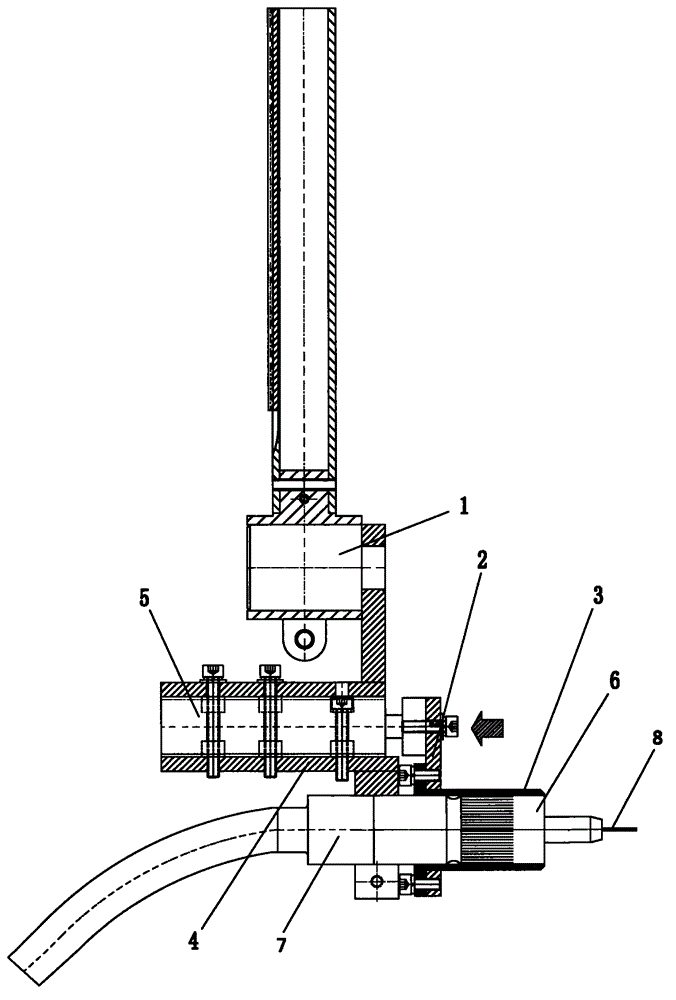
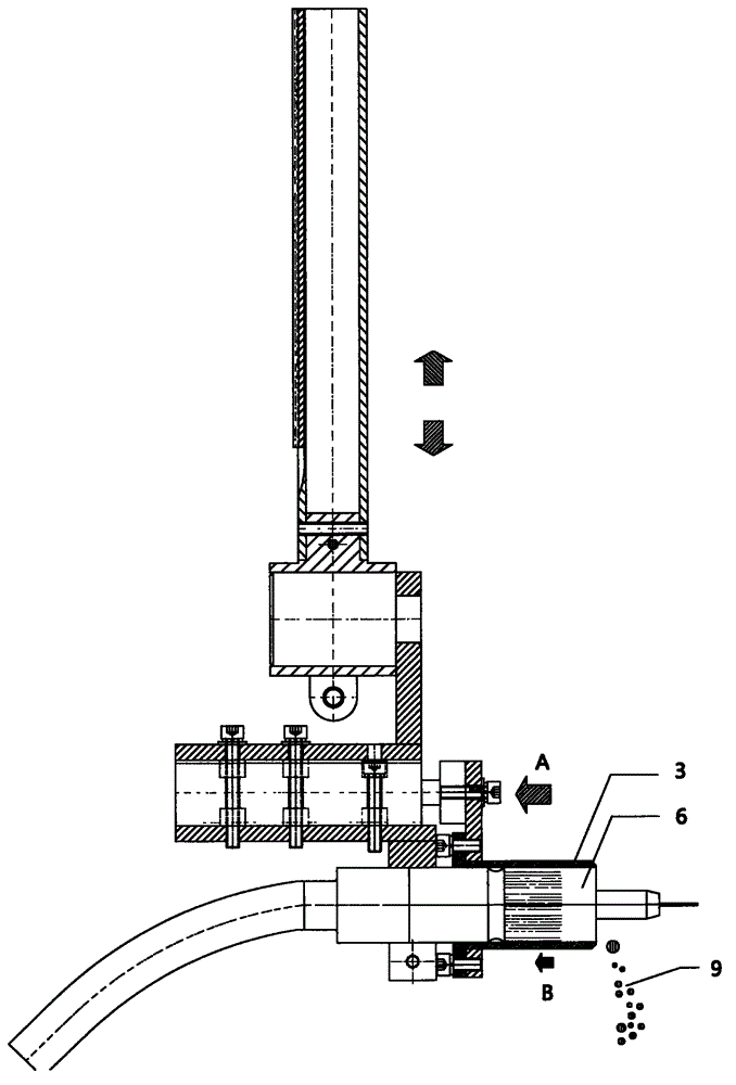
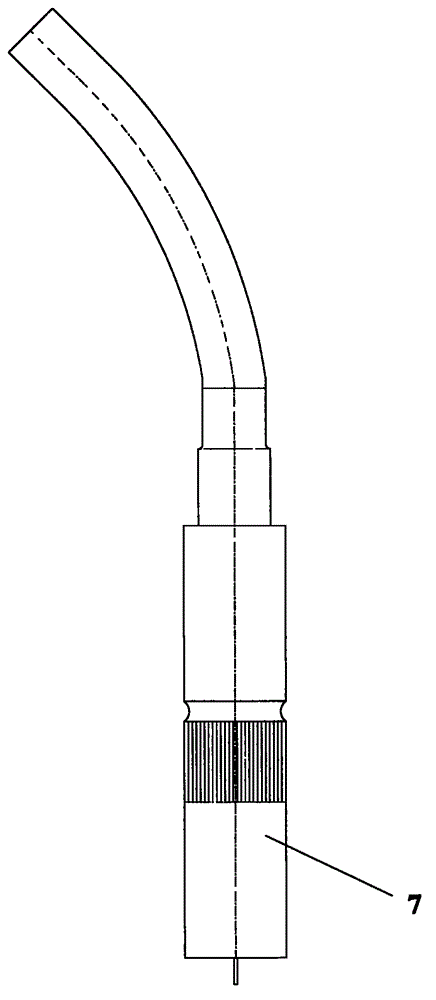
[0022] refer to Figure 1-3 Shown is a preferred embodiment of the present invention, which involves a CO 2 The standard welding torch (abbreviation welding torch 7) of the welding machine has a carbon dioxide inner protective cover 6 at the welding wire outlet end of the welding torch, and its outer circumference is equipped with a carbon dioxide outer protective cover 3, and the carbon dioxide outer protective cover 3 is fixed on the outer protective cover seat 2. The outer protection cover seat 2 is connected on the welding torch cylinder 5, the welding torch clamp 4 is equipped with the welding torch cylinder 5 lower sides, the welding torch clamp 4 is equipped with a carbon dioxide protection welding torch, and the outer circumference of the carbon dioxide inner protection cover 6 of its front end is covered wit...


PUM


Abstract

The invention relates to an automatic slag removal mechanism of a welding torch of a full-automatic CO2 (carbon dioxide) welding machine. The automatic slag removal mechanism comprises a CO2 inner protective sleeve, a CO2 outer protective sleeve and at lease one driving device, wherein the CO2 inner protective sleeve is arranged at the welding wire outlet end of the welding torch, the CO2 outer protective sleeve is sheathed on the CO2 inner protective sleeve and moves relative to the CO2 inner protective sleeve in the axial direction, the driving device is used for driving the CO2 inner protective sleeve and the CO2 outer protective sleeve to relatively move in the axial direction, the driving device comprises a welding torch air cylinder, the welding torch air cylinder is used for driving the CO2 outer protective sleeve to move back and forth between a first working station and a second working station, one end of the CO2 inner protective sleeve is fixedly connected with the welding torch, the other end of the inner protective sleeve at the first working station is inserted into the outer protective sleeve, and the other end of the inner protective sleeve at the second working station extends out of the outer protective sleeve. The automatic slag removal mechanism has the advantages that the structure is simple, the operation is easy and convenient, and the working efficiency is high; and the welding slag generated in the working process of the CO2 welding machine is automatically removed, and the poor welding effect which is caused by the welding slag being adhered to the interior of the CO2 inner protective sleeve and blocking the flowing out of the CO2 protective gas is avoided.

Description

technical field [0001] The invention relates to a welding torch applied to a welding machine, in particular to a fully automatic CO 2 Automatic slag removal mechanism for the welding torch of the welding machine. Background technique [0002] CO 2 The welding machine is a kind of welding machine commonly used in the current machinery industry, which provides a very important welding method for large and small manufacturing industries. CO 2 The welding method of the welding machine is that there is an automatic feeding welding wire in the center of a welding torch, and there is a protective cover for conveying carbon dioxide outside it. The function of carbon dioxide is to isolate the air to ensure that the weld bead is not oxidized during the welding process to maintain the welding strength of the welded workpiece. However, due to the high temperature during welding, welding slag will be generated, and the welding slag will splash around and fly into the In the carbon di...

Claims


Application Information

Patent Timeline
Patent Type & Authority Applications(China)
IPC IPC(8): B23K9/32B08B1/00
Inventor 邬文荣
Owner 嘉州包装机材(常熟)有限公司
Why Eureka
Eureka Blog
Learn More