A dual-discharge high-pressure manifold for fracturing

A technology of high-pressure manifolds and pressure relief pipes, which is applied in the fields of mining fluids, wellbore/well components, earthwork drilling, etc., can solve the problems of reduced water power efficiency of pump trucks, single structure and function, and reduced suction performance, etc., to achieve protection The effects of safe construction work, firm support positioning, and improved suction performance

Active Publication Date: 2015-09-09
中石化四机石油机械有限公司 +2
View PDF7 Cites 2 Cited by
  • Summary
  • Abstract
  • Description
  • Claims
  • Application Information

AI Technical Summary

Problems solved by technology

The problems existing in the existing discharge manifold mainly include: (1) Since the plunger pump has five water inlets, under the condition of large displacement, the flow rate of the single-discharge high-pressure manifold structure is very high, and it is easy to cause the discharge end of the pump head body to be damaged. Early damage; (2) As the distance between the suction end and the discharge port increases, the suction performance of the five suction ends of the plunger pump gradually decreases; (3) The single-discharge high-pressure manifold pipeline can only be fixed by the support of the ground. Under heavy working conditions, the pipeline is prone to violent vibration, which will cause damage to the connecting bolts of the discharge flange and premature failure of the discharge flange
When the single-discharge high-pressure manifold structure works under high-pressure and large-displacement conditions, the structure and function are single, and the displacement is greatly limited, which reduces the water power efficiency of the pump truck and is difficult to meet the fracturing requirements under large-displacement conditions.

Method used


Image

  • A dual-discharge high-pressure manifold for fracturing
  • A dual-discharge high-pressure manifold for fracturing

Examples


Embodiment Construction

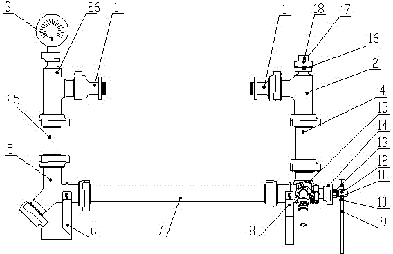
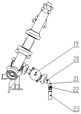
[0017] Attached below figure 1 and 2 , the present invention will be further described.

[0018] A dual-discharge high-pressure manifold for fracturing includes a discharge flange assembly 1, a T-shaped tee-2, a Martin Deck meter 3, a double-male variable-diameter joint-4, a Y-shaped tee 5, and a Y-shaped tee bracket 6. Integral double male straight pipe assembly 7, four-way joint bracket 8, four-way joint assembly 15, conversion joint 16, sensor joint 17, pressure sensor 18, T-shaped tee two 26, double male reducing joint two 25, by Plug valve 19, male union 20, elbow 21, pipe clamp 22 and steel wire reinforced steam pipe 23 form pressure relief manifold Ⅰ, which consists of steam cloth hose 9, stainless steel hose clamp 10, hose joint 11, needle valve 12 1. The male union needle valve joint 13 and the special-shaped nut 14 form the pressure relief manifold II, wherein the plug valve 19 in the pressure relief manifold I is connected with the male union 20, and the other end...


PUM


Abstract

The invention provides a double-discharging high pressure pipe manifold for fracturing. A first pressure relief pipe manifold and a second pressure relief pipe manifold are respectively connected at two ends of a four-way connection assembly, the other two ends of the four-way connection assembly are respectively connected with a first dual male reducer union and an integral dual male straight pipe assembly, one end of the integral dual male straight pipe assembly is connected with a Y-shaped tee joint, a second dual male reducer union and a second T-shaped tee joint in sequence, the other two ends of the second T-shaped tee joint are respectively connected with a Marti-Decker gauge and a discharging flange assembly, the other end of the first dual male reducer union is connected with a first T-shaped tee joint and the discharging flange assembly in sequence, and the other end of the first T-shaped tee joint is connected with an adapter, a transducer adapter and a pressure sensor in sequence. The double-discharging high pressure pipe manifold is capable of overcoming the defects and disadvantages of existing discharging pipe manifolds. Further, the structural functions of the discharging pipe manifold are increased, and the water power efficiency of a fracturing pump truck is improved.

Description

technical field [0001] The invention belongs to the field of petroleum equipment, in particular to a discharge manifold system for fracturing. Background technique [0002] In the development process of conventional oil and gas fields, it is often necessary to fracture the reservoir to obtain better oil and gas passages after the oil and gas wells enter the late stage of production to increase the production of single wells. In unconventional oil and gas exploration operations, due to special geological conditions, the Most gas reservoirs have extremely low porosity and permeability, and the reservoirs must be fractured to obtain industrial oil and gas flow. Fracturing equipment is the necessary equipment for fracturing the reservoir. The fracturing equipment is composed of fracturing truck, sand mixing truck, manifold truck, instrument truck and auxiliary equipment. During construction, the fracturing fluid passes through the fracturing The fracturing plunger pump on the f...

Claims


Application Information

Patent Timeline
Patent Type & Authority Patents(China)
IPC IPC(8): E21B43/26
Inventor 王云海吴汉川彭平生李莉莉刘灼柳庆仁范杰陈勇
Owner 中石化四机石油机械有限公司
Why Eureka
Try Eureka