
Phase separation micro-channel condenser

A micro-channel and condenser technology, applied in indirect heat exchangers, cooling/ventilation/heating transformation, lighting and heating equipment, etc., can solve the problems of uncontrollable two-phase flow pattern, and reduce flow resistance and flow instability The effects of stability, thinning liquid film thickness, and improving condensation heat transfer performance

Active Publication Date: 2015-06-10
NORTH CHINA ELECTRIC POWER UNIV (BAODING)
View PDF5 Cites 1 Cited by
  • Summary
  • Abstract
  • Description
  • Claims
  • Application Information

AI Technical Summary

Problems solved by technology

Usually, traditional microchannel condensers cannot control the two-phase flow pattern. In order to improve the thermal efficiency of the system and reduce its volume, it is urgent to develop microchannel evaporators and condensers with high heat transfer performance.

Method used


Image

  • Phase separation micro-channel condenser
  • Phase separation micro-channel condenser
  • Phase separation micro-channel condenser

Examples


Embodiment

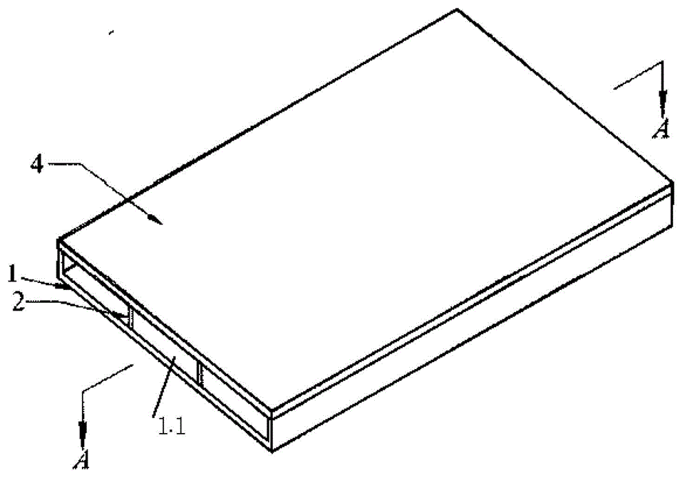
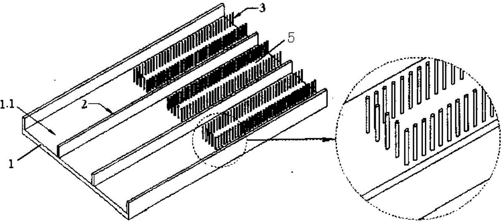
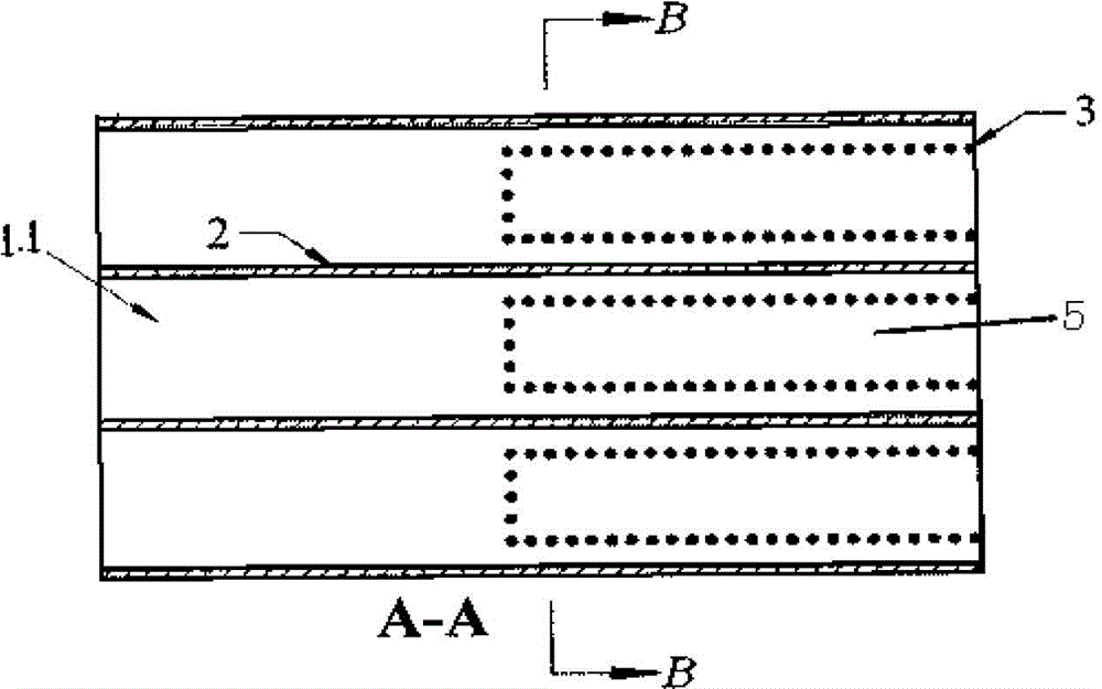
[0021] figure 1 , figure 2 Shown is a schematic structural view of the phase separation microchannel condenser of the present invention. The phase-separated microchannel condenser shown in the figure is to etch a plurality of parallel microchannels 1.1 on the silicon substrate 1, and the microchannels are separated by ribs 2; a large amount of microchannels are etched in the downstream area 5 of the microchannels Ribs 3, and surround openings towards the rib network downstream; the top of the microchannel is encapsulated by a cover plate 4; the external structure of the phase-separated microchannel condenser is as follows figure 1 As shown, the internal structure is as figure 2 , image 3 and Figure 4 shown. The phase-separated micro-channel condenser first processes a plurality of parallel micro-channels 1.1 on a semiconductor silicon substrate 1 through an etching process, and the silicon substrate 1 is a cooling surface at the bottom of the micro-channels. The widt...


PUM


Abstract

The invention discloses a phase separation micro-channel condenser and belongs to the field of the heat transfer enhancement technology. A plurality of parallel micro-channels are etched on a silicon substrate and are separated by rib sheets. A plurality of rib strips are etched in the downstream area of each micro-channel. The rib strips of each micro-channel form, in an enclosing mode, a rib strip net with an opening toward the downstream. A cover plate packages on the micro-channels. The phase separation micro-channel condenser overcomes the defect that a traditional micro-channel condenser can not modulate a two phase flow pattern. Different from other reinforcing condensing heat conduction devices, due to the fact that an air phase and a liquid phase flow in branch paths after flow pattern modulation, the phase separation micro-channel condenser can greatly reduce the thickness of a liquid film, improve condensing heat exchange performance, reduce flow resistance and flow instability, and be applied to an electronic element heat-sink cooling system.

Description

technical field [0001] The invention belongs to the technical field of enhanced heat exchange, in particular to a phase-separated microchannel condenser. Specifically, it is an enhanced heat exchanger for the heat dissipation and cooling system of electronic components. Background technique [0002] In recent years, with the rapid development of the electronics industry, the integration of electronic circuits has been greatly improved, and the heat generation has been increasing. People urgently need to develop heat dissipation and cooling systems for electronic components with high heat flux. [0003] During the condensation process in the microchannel, the vapor-liquid two-phase mainly exists in annular flow, slug flow and bubbly flow. At the entrance of the microchannel, the gas-liquid two-phase presents an annular flow pattern, and the condensation heat transfer performance is good; as the condensation progresses, the flow pattern gradually changes from an annular flow ...

Claims


Application Information

Patent Timeline
Patent Type & Authority Patents(China)
IPC IPC(8): F28D15/02H05K7/20
Inventor 孙东亮徐进良陈奇成
Owner NORTH CHINA ELECTRIC POWER UNIV (BAODING)
Learn More