[0050] The specific embodiments of the present invention will be further described in detail below in conjunction with the accompanying drawings.
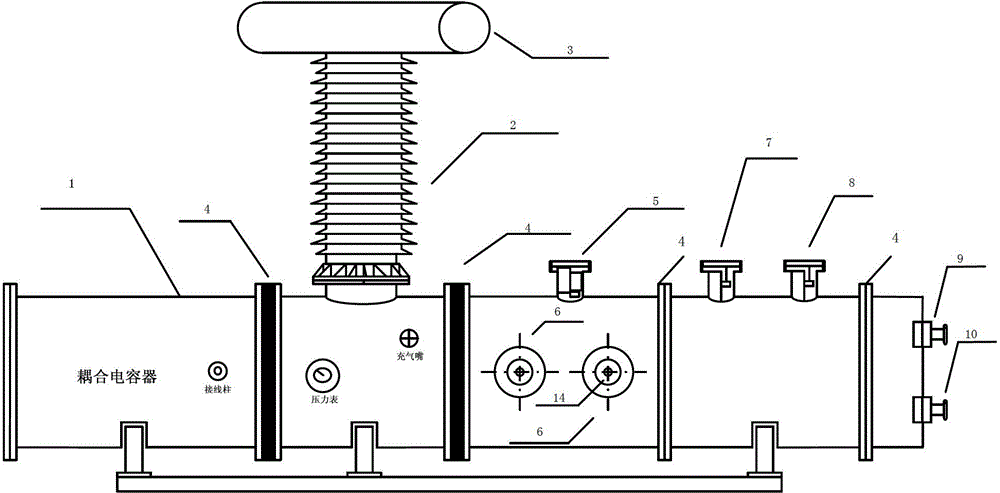
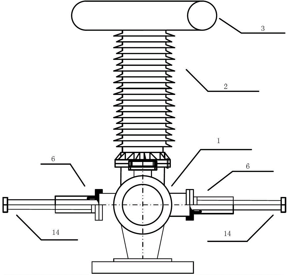
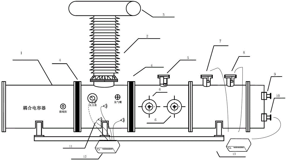
[0051] Such as figure 1 As shown, figure 1 It is the front view of the GIS partial discharge ultrasonic and UHF sensor detection and calibration system; in the figure, the GIS partial discharge ultrasonic and UHF sensor detection and calibration system includes GIS tanks, high voltage bushings, pressure equalizing rings, basin insulators, built-in cameras, GIS Partial discharge model, standard UHF sensor, UHF sensor to be tested, ultrasonic signal injection port and UHF signal injection port.
[0052] The GIS tank is perpendicular to the high-voltage casing and connected at the lower end. The upper end of the high-voltage casing is equipped with a pressure equalizing ring. The GIS tank is symmetrically equipped with basin insulators on both sides of the high-voltage casing and the standard UHF sensor and the UHF sensor to be tested. Connection to the tank; the surface of the GIS tank at the symmetry of the high-voltage bushing is equipped with a support seat; the surface of the GIS tank between the basin insulators is equipped with a pressure gauge and a gas filling nozzle, and coupling capacitors and GIS parts are built in on both sides. Discharge model, the coupling capacitor is connected with the terminal installed on the outer surface of the GIS tank; the GIS partial discharge model is a two-pair symmetrical and vertical connection to the outside of the GIS tank; the upper part of the GIS partial discharge model is equipped with infrared high-definition to observe the inside of the GIS tank Camera. One side of the camera is equipped with a standard UHF sensor and a UHF sensor to be tested. When measuring, the standard UHF sensor and the UHF sensor to be tested are respectively installed in the standard UHF sensor hole and the UHF sensor hole to be tested. The UHF sensor holes are on the same axis of the GIS tank; that is, the standard UHF sensor and the UHF sensor to be tested are on the same axis of the tank during measurement; an ultrasonic signal injection port and a UHF signal injection port are provided at one end of the GIS tank. Among them, the terminal is connected with the partial discharge detection device.
[0053] Such as figure 2 As shown, figure 2 It is a side view of the GIS partial discharge ultrasonic and UHF sensor detection and verification system; the GIS partial discharge model is a push rod GIS partial discharge model. Before the GIS tank is filled with SF6 gas, the push rod GIS partial discharge model is placed in the tank. Since there are multiple GIS partial discharge models arranged in the GIS tank, one test only tests one or several of these models. When testing the selected GIS partial discharge model, only the corresponding The push rod advances forward, and the push rod movement does not affect the overall air tightness of the GIS tank. Observe whether the model is in place through the built-in camera. The external surface of the GIS tank is equipped with a terminal, which is connected to the built-in coupling capacitor of the GIS tank, and can be connected with the partial discharge detection equipment to detect the partial discharge signal; the surface of the GIS tank is equipped with a pressure gauge to monitor the SF6 gas pressure, and the gas filling and discharging nozzle Used to fill or extract SF6 gas into the GIS tank.
[0054] In the GIS partial discharge ultrasonic sensor testing and verification system, the ultrasonic sensor to be tested and the standard ultrasonic sensor are symmetrically arranged on the surface of the GIS tank. The GIS partial discharge model generates ultrasonic signals when partial discharge occurs. The performance of the sensor under test is evaluated by comparing the measurement signal of the ultrasonic sensor under test with the measurement signal of the standard ultrasonic sensor. In addition, an ultrasonic signal with known characteristics can be injected into the GIS tank at the ultrasonic signal injection port 9, and the performance of the sensor under test can be evaluated by comparing the measurement signal of the ultrasonic sensor under test with the measurement signal of the standard ultrasonic sensor.
[0055] In the GIS partial discharge UHF sensor detection and calibration system, the UHF sensor to be tested and the standard UHF sensor are installed in the designated position of the GIS tank. The GIS partial discharge model generates UHF signals when a partial discharge occurs. The performance of the sensor under test can be evaluated by comparing the measurement signal of the UHF sensor under test with that of the standard UHF sensor. In addition, a UHF signal with known characteristics can be injected into the UHF signal injection port 10 into the GIS tank, and the performance of the sensor under test can be evaluated by comparing the measurement signal of the UHF sensor under test with the measurement signal of the standard UHF sensor.
[0056] Such as image 3 As shown, image 3 GIS partial discharge ultrasound, UHF sensor positioning system testing and verification system diagram; the system also includes an ultrasonic partial discharge positioning system 12 and a UHF partial discharge positioning system 13; during testing, the ultrasonic sensor 11 is attached to the surface of the GIS tank; The partial discharge positioning system 12 is connected to the ultrasonic sensor; the UHF partial discharge positioning system 13 is connected to the UHF sensor to be tested, the standard UHF sensor and the UHF signal injection port. The measurement terminals of the ultrasonic sensor and the UHF sensor are connected to the oscilloscope. This inspection and verification system measures and records its reference coordinates relative to the tank body when a typical GIS discharge model is installed. Different discharge models can be used to simulate the discharge at different coordinate points. The number and position of the ultrasonic sensors 11 can be selected by the manufacturer. The sensors are connected to the positioning system through a feeder to carry out an error test between the positioning of the ultrasonic positioning system and the actual discharge position to check and verify the positioning The sensitivity of the system (positioning detection can be carried out in large amounts) and positioning accuracy. Before UHF positioning system testing and verification, the UHF sensor needs to be installed with 8 holes for the UHF sensor to be tested. UHF signal injection port 10 is equipped with a UHF sensor to emit UHF signals. This hole is required when the test conditions require (such as UHF positioning research) Other (such as positioning) UHF sensors can also be installed.
[0057] GIS partial discharge ultrasonic, UHF sensor detection and verification system corresponds to GIS partial discharge ultrasonic detection and verification method and UHF sensor detection and verification method; among them,
[0058] GIS partial discharge ultrasonic testing and verification methods include two methods;
[0059] Method one includes the following steps: the ultrasonic signal injection port 9 injects an ultrasonic signal with known waveform characteristics, and symmetrically distributes the ultrasonic sensor to be tested and the standard ultrasonic sensor on the surface of the GIS tank 1, and the measurement terminals of the two are connected to the oscilloscope through both The measurement results are compared and analyzed to detect and verify the performance of the ultrasonic sensor under test when the characteristics of the ultrasonic source are known.
[0060] Method two includes the following steps: externally pressurize through the high-voltage bushing 2, the GIS partial discharge model 16 generates a partial discharge excitation ultrasonic signal, the ultrasonic sensor to be tested and the standard ultrasonic sensor are symmetrically distributed on the surface of the GIS tank 1, and the measurement terminals of both It is connected with an oscilloscope, through the comparison and analysis of the measurement results of the two, to detect and verify the performance of the ultrasonic sensor under test in a situation similar to the actual GIS partial discharge.
[0061] The sensitivity of the standard sensor is known. Through the excitation of the same ultrasound source (partial discharge excitation), the sensitivity can be obtained by comparing the detection results of the ultrasonic sensor to be tested and the standard sensor.
[0062] This system can generate partial discharges through different discharge models, apply voltages, measure ultrasonic signal spectrograms of different discharge types, establish an expert database after graphic identification, and provide identification comparison sources for subsequent GIS partial discharge fault type diagnosis for identification Different types of insulation defects.
[0063] GIS partial discharge UHF sensor detection and calibration method;
[0064] UHF sensor sensitivity is an important parameter of the GIS partial discharge online monitoring system. Using the GIS partial discharge UHF sensor detection and calibration system can realize UHF sensor sensitivity detection, including the following:
[0065] Step 1: Use a discharge model inside the GIS tank to simulate GIS partial discharge faults. The GIS partial discharge model is pressurized and discharged through the equalizing ring to generate partial discharge faults.
[0066] Due to different types of faults, different types of sensors, and different locations, all have an impact on the UHF measured spectrogram; therefore, while carrying out the UHF sensor detection and calibration work, it is necessary to clarify the above three variables (ie, fault type, sensor type, Sensor position), usually take the same type of discharge fault, the same type of sensor for comparison, the UHF sensor position is fixed during system design.
[0067] The GIS fault simulation platform can realize the comparison test of UHF sensors at similar positions, and the selected GIS partial discharge model is fixed in place by its push rod 14, and the tie rods of other models are pulled out accordingly. The other models are those that are built into the GIS tank but do not participate in the partial discharge test. For example, when testing the left model, push the left lever instead of pushing the right and symmetrical two Putts.
[0068] Step 2: When a partial discharge fault occurs, simultaneously record the spectrogram received by the two sensors through an oscilloscope, and save the spectrogram into the computer; obtain the actual discharge volume through the partial discharge detector; the two UHF sensors are arranged in the UHF sensor hole to be tested and standard UHF sensor hole.
[0069] Step 3: Use a nanosecond pulse generator to inject artificial partial discharge pulses through the UHF signal injection port 10, record the spectrogram received by the UHF sensor through an oscilloscope, and save the spectrogram to the computer; obtain the apparent discharge through the partial discharge detector the amount.
[0070] Step 4: Compare with the spectrogram recorded by the UHF sensor in the first step, and adjust the amplitude and rise time of the nanosecond pulse generator to make the comparison error of the spectrogram within ±20%, then adjust The nanosecond pulse generator is used as the repetitive discharge pulse source, and the frequency of the repetitive discharge pulse source can be 50HZ;
[0071] Step 5: The relationship between the nanosecond pulse generator and the partial discharge (pC) established through the above test. The adjusted nanosecond pulse generator can repeatedly generate the previously confirmed apparent discharge. Type UHF sensor or sensor that has been installed on the on-site GIS, inject repetitive discharge pulses into the GIS tank, and compare the detection results of the UHF sensor to be inspected with the standard UHF sensor. If the spectrogram can be detected, the sensor has the specified Sensitivity detection capability.
[0072] The apparent discharge capacity is specified here. Through the adjustment of the discharge model in the detection room, the partial discharge apparent discharge capacity can be lowered and the UHF sensor with higher sensitivity can be detected. When the sensor to be checked meets the UHF sensor tooling design of the GIS partial discharge fault simulation device, the detection and verification of a variety of different types of sensors can be realized.
[0073] Step 6: Obtain a spectrogram, and compare and analyze the sensitivity performance of the UHF sensor.
[0074] The sensitivity detection method can detect the minimum sensitivity value of the UHF sensor in the detection room. At the same time, the repetitive artificial nanosecond pulse source obtained by the modulation in the detection room can be used for the calibration of the UHF sensor installed on site and the debugging of the test loop. When there are more than two types of sensors in the on-site GIS partial discharge UHF online monitoring, the installation method and position of the on-site UHF sensor can be simulated by the tooling of the GIS fault simulation platform in the detection room, and it can be modulated for repeatable acceptance of the same type of UHF sensor calibration on site Second pulse source.
[0075] This system generates partial discharges through different discharge models, applies voltages, measures UHF spectrograms of different discharge types, and establishes an expert database after graphic identification to provide identification and comparison sources for subsequent GIS partial discharge fault type diagnosis to identify different insulation Defect type.
[0076] GIS partial discharge ultrasonic, UHF sensor positioning system detection and calibration system corresponding to the detection and calibration methods include: select the reference coordinate origin before the test, measure and record the coordinates of the discharge point; simulate single-point discharge, multi-point discharge in actual GIS Select the different GIS partial discharge models developed; use the partial discharge ultrasound and UHF positioning system of the GIS under test to measure, compare the positioning results with the recorded discharge point coordinates, and make a comparative analysis of errors.
[0077] In practice, the partial discharge point of GIS is arbitrary, and the positioning errors of products produced by different manufacturers are not easy to compare when positioning, so that it is impossible to compare the advantages and disadvantages of the performance of the products of various manufacturers. The GIS partial discharge ultrasonic positioning detection and inspection system simulates the actual partial discharge of the GIS, but the position of the discharge point is known, so it can provide a platform for performance comparison of products produced by different manufacturers.
[0078] Finally, it should be noted that the above embodiments are only used to illustrate the technical solutions of the application and not to limit the scope of protection. Although the application has been described in detail with reference to the above embodiments, those of ordinary skill in the art should understand: Those skilled in the art can still make various changes, modifications or equivalent substitutions to the specific implementation of the application after reading this application, but these changes, modifications or equivalent substitutions are all within the protection scope of the pending claims of the application.