High Speed Motor System
A high-speed motor, AC motor technology, applied in the magnetic circuit shape/pattern/structure, the magnetic circuit static parts, the shape/pattern/structure of the winding conductor, etc., can solve the problem of increasing the system volume and loss, and the damping effect is difficult to achieve optimal and other issues to achieve the effect of reducing high-frequency loss, low cost, and increasing leakage reactance
- Summary
- Abstract
- Description
- Claims
- Application Information
AI Technical Summary
Problems solved by technology
Method used
Image
Examples
specific Embodiment approach 1
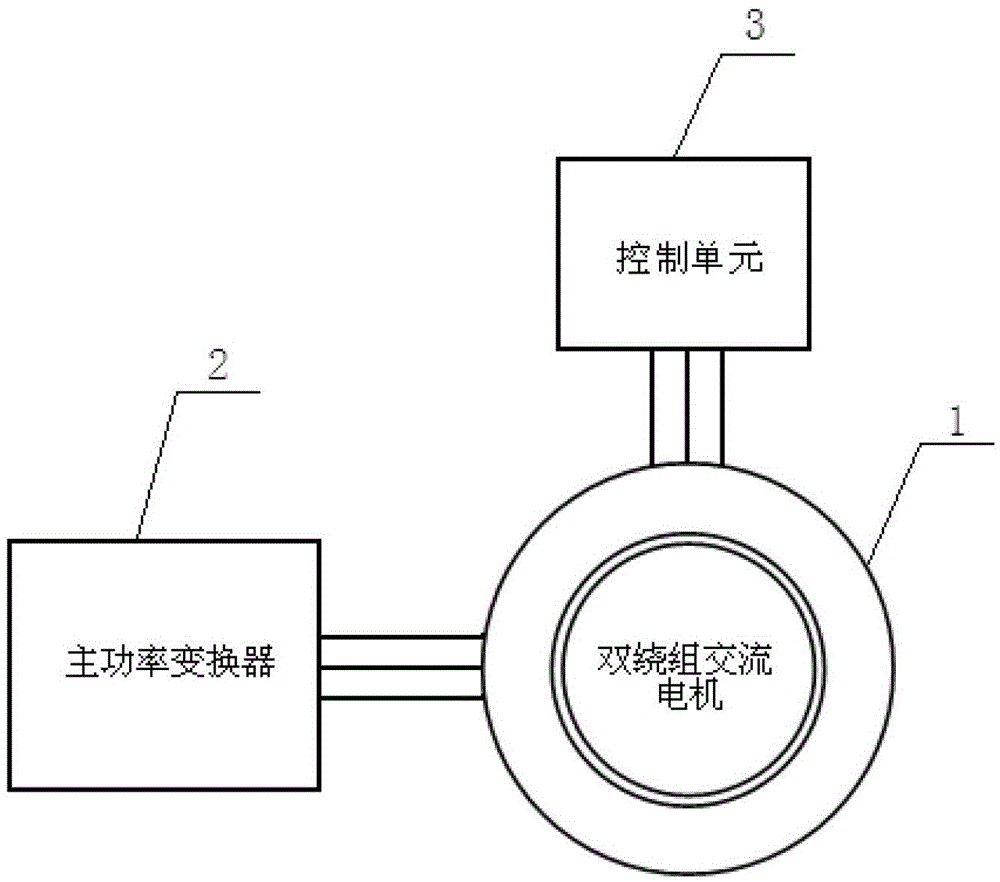
[0023] Specific implementation mode one: the following combination image 3 Describe this embodiment mode, the high-speed motor system described in this embodiment mode, it comprises double-winding AC motor 1, main power converter 2 and control unit 3;
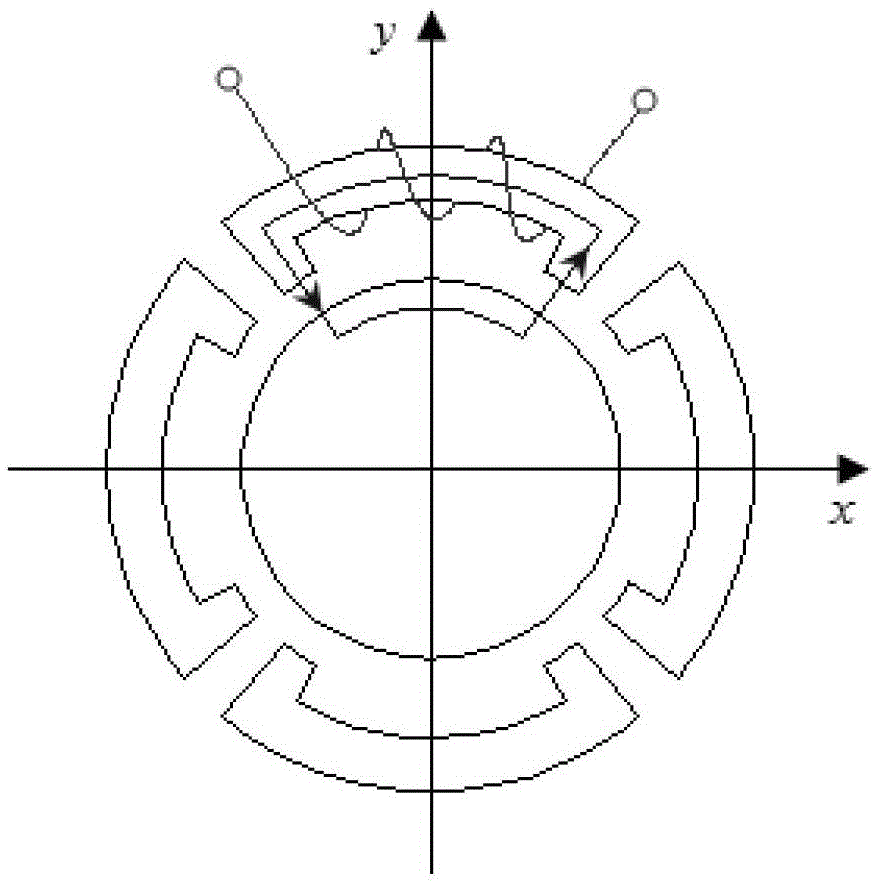
[0024] The double-winding AC motor 1 includes a stator and a rotor, the stator includes a stator core and a stator winding, the stator core is cylindrical, and the stator winding is a double-winding structure composed of a main winding and an auxiliary winding;
[0025] The lead wire of the main winding is connected to the main power converter 2;
[0026] The secondary winding leads are connected to the control unit 3 .
[0027] The two-winding AC motor 1 can be a synchronous motor, an induction motor or a reluctance motor
specific Embodiment approach 2
[0028] Specific implementation mode two: the following combination Figure 4 Describe this embodiment, this embodiment will further describe Embodiment 1, the control unit 3 includes a vibration signal processing unit, an inverter circuit and a controller,
[0029] The vibration signal processing unit receives the vibration signal output by the auxiliary winding, the data processed by the vibration signal processing unit is output to the controller, the controller outputs control instructions to the inverter circuit, and the inverter circuit outputs the control current for the auxiliary winding.
[0030] In this embodiment, the vibration signal output by the secondary winding is collected and processed by the vibration signal processing unit, and the processed signal is output to the controller, and the controller outputs corresponding control instructions to the inverter circuit according to the input data, and the inverter circuit outputs The control current is fed back to t...
specific Embodiment approach 3
[0033] Specific implementation mode three: the following combination Figure 6 to Figure 8 Describe this embodiment, this embodiment will further explain Embodiment 1, the main winding is a star structure, the number of coils of the main winding is an even number; The output terminals are connected; the secondary winding lead wire is connected to the detection signal input terminal of the control unit 3;
[0034] Control unit 3 comprises vibration signal processing unit, inverter circuit and controller,
[0035] The vibration signal processing unit receives the vibration signal of the secondary winding, the data processed by the vibration signal processing unit is output to the controller, and the controller outputs control instructions to the inverter circuit, and the output end of the inverter circuit is used as the output end of the control unit 3 .
[0036] In this embodiment, the control command output by the inverter circuit is fed back to the middle point of the coil s...
PUM
 Abstract
Description
Claims
Application Information
 - R&D
- Intellectual Property
- Life Sciences
- Materials
- Tech Scout
- Unparalleled Data Quality
- Higher Quality Content
- 60% Fewer Hallucinations
Browse by: Latest US Patents, China's latest patents, Technical Efficacy Thesaurus, Application Domain, Technology Topic, Popular Technical Reports.
© 2025 PatSnap. All rights reserved.Legal|Privacy policy|Modern Slavery Act Transparency Statement|Sitemap|About US| Contact US: help@patsnap.com


