
Continuous grid roller shear slicing system

A grid and rolling shear technology, applied in shearing devices, shearing machine equipment, accessories of shearing machines, etc., can solve the problems of waste, irregular cutting, polluted materials, etc., to reduce production costs, improve production efficiency, The effect of reducing the scrap rate

Active Publication Date: 2013-10-09
中国船舶重工集团衡远科技有限公司
View PDF4 Cites 9 Cited by
  • Summary
  • Abstract
  • Description
  • Claims
  • Application Information

AI Technical Summary

Problems solved by technology

[0002] The grid is the main component of the lead-acid battery. The traditional grid is cast in a single piece. Due to the use of a single piece of casting, the processing efficiency of this grid is not high, and it is easy to cause the lead alloy to leak during the processing and cause Environmental pollution and waste of materials, therefore, single-piece grids are gradually replaced; now the casting of grids generally adopts continuous grids, expanded grids and flushed grids. For continuous grids, it is greatly The processing efficiency and material utilization rate of the grid are improved, but the problem faced by the continuous grid is that it needs to be cut, and the existing equipment for shearing the continuous grid has the following deficiencies. First, in the cutting process, due to In the cutting process, there are factors of uneven force, which cause the deformation of the grid, and the cutting is not neat, which leads to a high scrap rate of the single grid after cutting, which seriously affects the production efficiency and product quality. Secondly, due to the existing The cutting accuracy of the cutting equipment for the continuous grid cannot be effectively guaranteed, resulting in uneven size of the single grid after cutting, which affects the performance of the lead-acid battery

Method used


Image

  • Continuous grid roller shear slicing system
  • Continuous grid roller shear slicing system
  • Continuous grid roller shear slicing system

Examples


Embodiment Construction

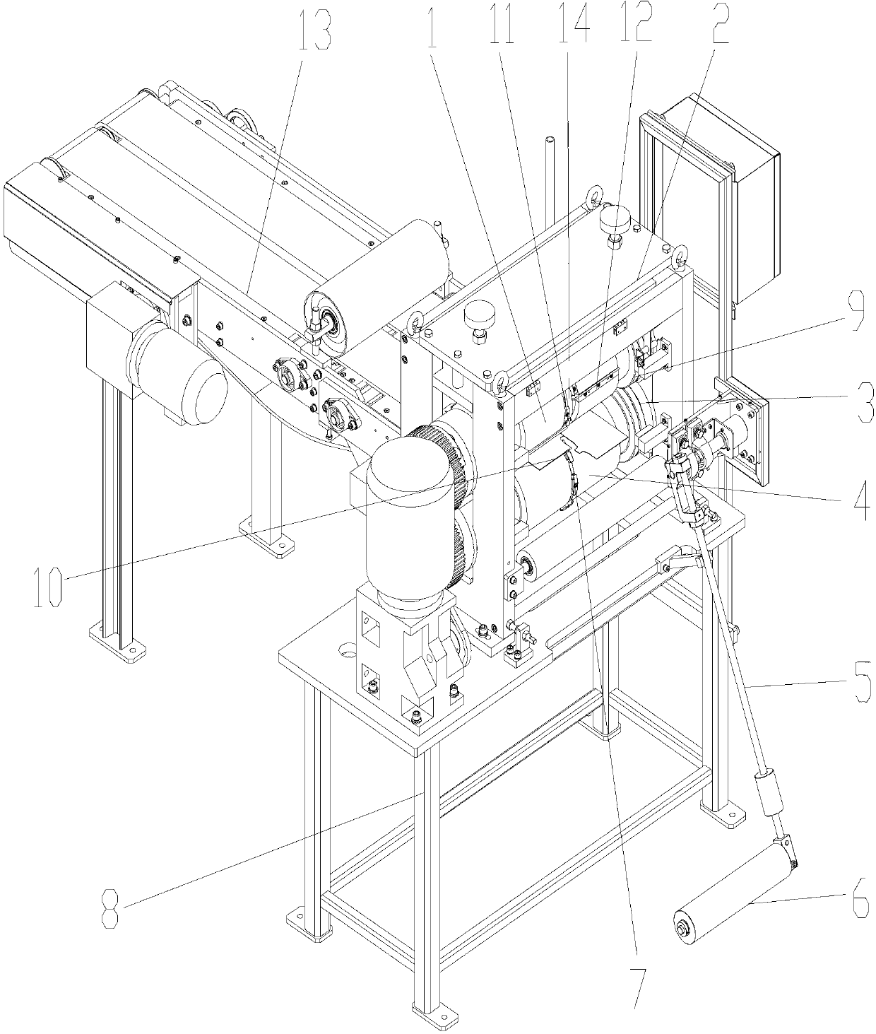
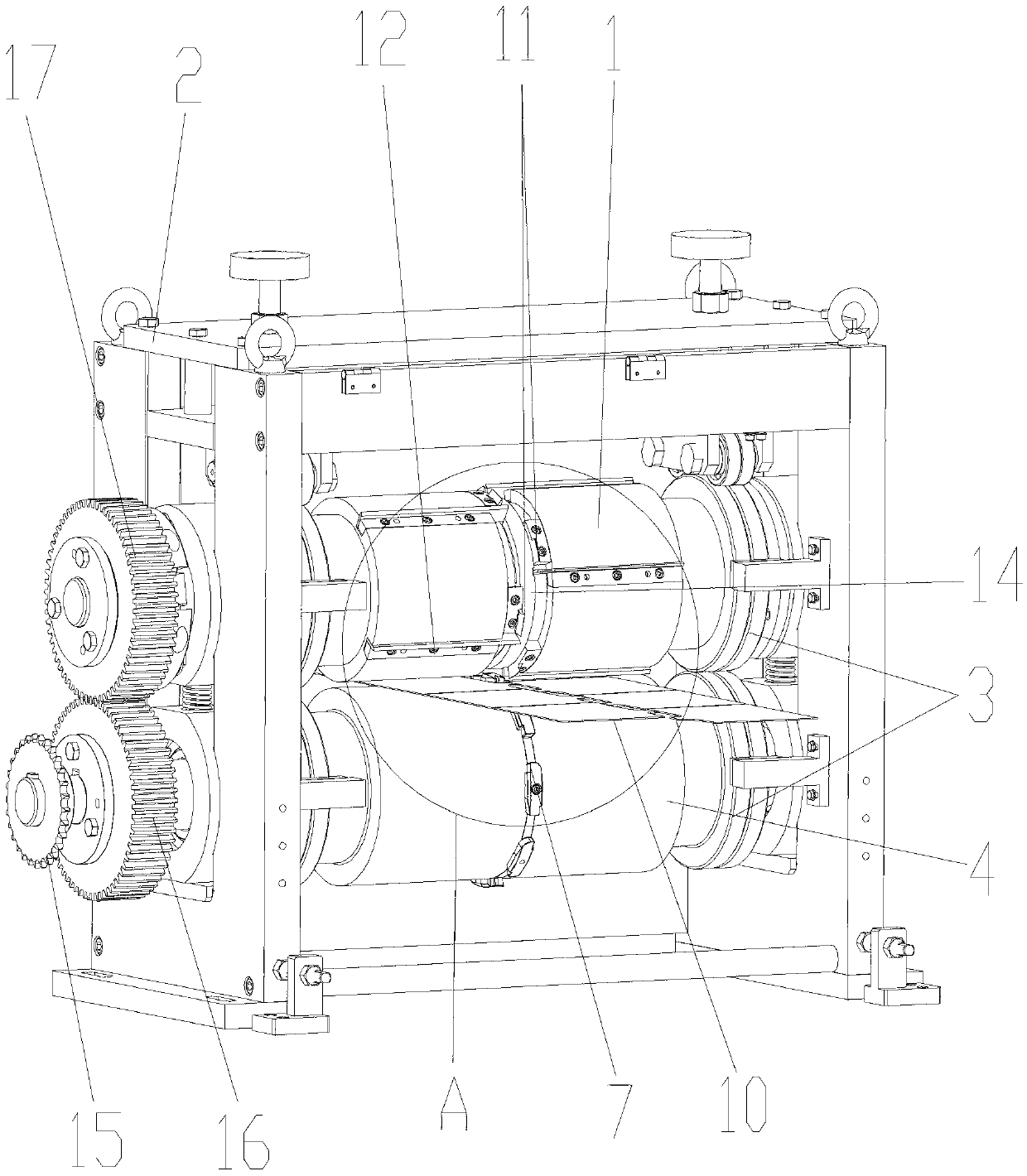
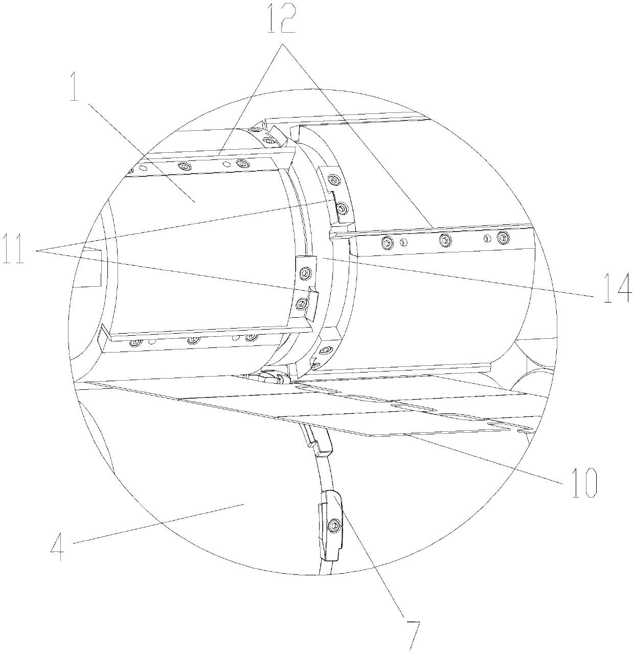
[0023] figure 1 It is a structural schematic diagram of the present invention, figure 2 It is a structural schematic diagram of the shearing device of the present invention, image 3 for figure 2 Enlarged view of A in the middle, Figure 4 Schematic diagram of the structure of the continuous grid, Figure 5 It is a structural schematic diagram of the fine-tuning device of the present invention, Figure 6 for Figure 5 The structure schematic diagram of the middle right view, as shown in the figure, a continuous grid rolling shear slicing system provided by the present invention at least includes a shearing device for slicing and shearing the continuous grid, and the shearing The device at least includes a cutter roller 1 arranged in the form of a pair of rollers and a power roller 4 for positioning the continuous grid 10 and providing power for the continuous grid 10 to advance. The circumferential direction of the cutter roller 1 is fixed and useful. The cutter is use...


PUM


Abstract

The invention provides a continuous grid roller shear slicing system. The continuous grid roller shear slicing system at least comprises a shearing device used for slicing and shearing a continuous grid. The shearing device at least comprises a cutter roll and a power roll, wherein the cutter roll and the power roll are arranged in a roll-pair mode, and the power roll is used for positioning the continuous grid and supplying power to the continuous grid. Cutters used for shearing the continuous grid into single slices are fixedly arranged on the cutter roll in the peripheral direction. The continuous grid roller shear slicing system can accurately position and shear the continuous grid, sizes of single-slice grids after the continuous grid is cut can be effectively guaranteed, and in addition, the whole system guarantees uniform stress on the continuous grid in the cutting process, and can effectively prevent deformation of the grid, effectively guarantee quality of the single-slice grids after the cutting process, greatly reduce rejection rates, improve production efficiency and reduce production cost.

Description

technical field [0001] The invention relates to a lead-acid battery grid slicing system, in particular to a continuous grid rolling shear slicing system. Background technique [0002] The grid is the main component of the lead-acid battery. The traditional grid is cast in a single piece. Due to the use of a single piece of casting, the processing efficiency of this grid is not high, and it is easy to cause the lead alloy to leak during the processing and cause Environmental pollution and waste of materials, therefore, single-piece grids are gradually replaced; now the casting of grids generally adopts continuous grids, expanded grids and flushed grids. For continuous grids, it is greatly The processing efficiency and material utilization rate of the grid are improved, but the problem faced by the continuous grid is that it needs to be cut, and the existing equipment for shearing the continuous grid has the following deficiencies. First, in the cutting process, due to In the...

Claims


Application Information

Patent Timeline
IPC IPC(8): B23D31/00B23D33/00B23D33/02B23D35/00B21D43/28
Inventor 叶荣卒袁鹄胡志宏汪浩然魏治千吴克海
Owner 中国船舶重工集团衡远科技有限公司
Features
  • Generate Ideas
  • Intellectual Property
  • Life Sciences
  • Materials
  • Tech Scout
  • Unparalleled Data Quality
  • Higher Quality Content
  • 60% Fewer Hallucinations
Learn More