Welding fixture for welding blade on rotor

A technology for welding tooling and rotors, applied in welding equipment, manufacturing tools, resistance welding equipment, etc., can solve problems such as accurate positioning of blades, achieve the effects of ensuring welding accuracy, improving welding quality, and shortening positioning time

Active Publication Date: 2013-10-09
苏州斯奥克微电机制造有限公司
View PDF6 Cites 10 Cited by
  • Summary
  • Abstract
  • Description
  • Claims
  • Application Information

AI Technical Summary

Problems solved by technology

Resistance spot welding needs to press the welding workpiece between two electrodes, and the blade cannot be positioned accurately with the rotor. It is very difficult to weld the blade on the rotor by resistance spot welding. Therefore, how to weld the blade on the rotor is a Difficulties that urgently need to be overcome

Method used


Image

  • Welding fixture for welding blade on rotor
  • Welding fixture for welding blade on rotor

Examples


Embodiment Construction

[0014] The following will clearly and completely describe the technical solutions in the embodiments of the present invention with reference to the drawings in the embodiments of the present invention.

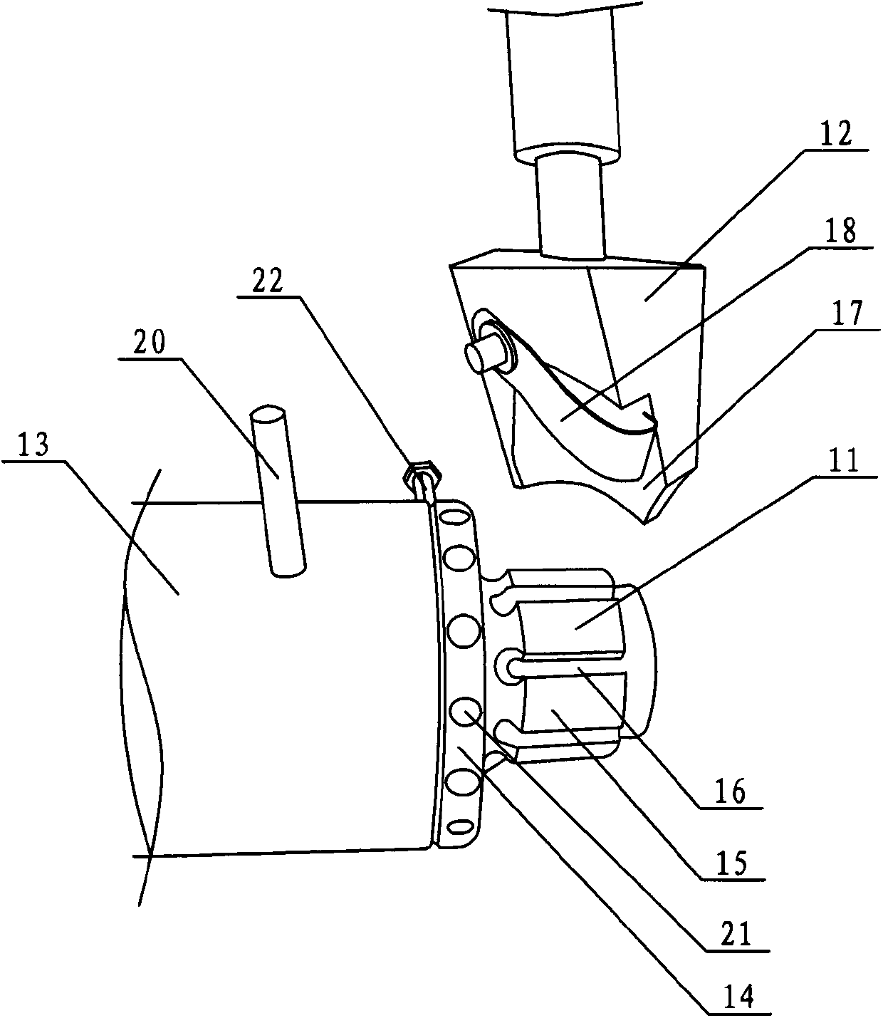
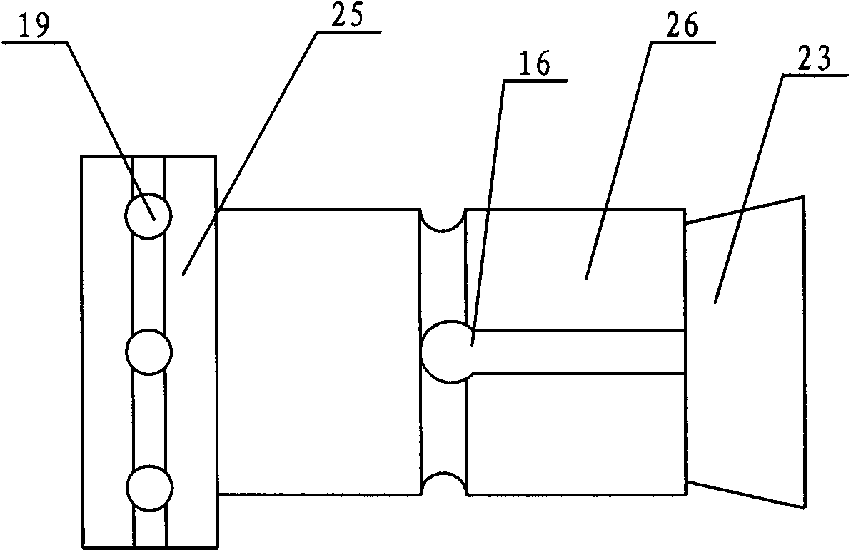
[0015] The invention provides a welding tool for welding the blades on the rotor (see figure 1 with 2 ), including a copper first electrode 11 and a second electrode 12, the first electrode 11 includes a fixed seat 13, a rotating disk 14 and a rotor bearing seat 15 arranged in sequence, and the rotating disk 14 is sleeved on the rotor bearing seat 15 and is connected with The fixed connection, the bump 25 at the front end of the rotor bearing base 15 is inserted into the fixing base 13, the rotor bearing base 15 rotates around the fixing base 13, the diameter of the bearing end 26 at the rear end of the rotor bearing base 15 matches the inner diameter of the rotor, and the bearing end 26 A positioning slot 16 for positioning the rotor is provided on the outer circle of the ro...


PUM


Abstract

The invention discloses a welding fixture for welding a blade on a rotor. The welding fixture for welding the blade on the rotor comprises a first copper electrode and a second copper electrode. The first electrode comprises a fixing seat, a rotary plate and a rotor bearing seat, wherein the fixing seat, the rotary plate and the rotor bearing seat are sequentially arranged; the rotary plate is sleeved on the rotor bearing seat and is fixedly connected with the rotor bearing seat; a protruding block at the front end of the rotor bearing seat is inserted in the fixing seat; the rotor bearing seat rotates around the fixing seat; the diameter of a bearing end at the rear end of the rotor bearing seat is matched with the inner diameter of the rotor; a positioning groove for positioning the rotor is formed in the outer circle of the bearing end; an accommodating groove for bearing the blade is arranged on the second electrode; a compression sheet for pressing the blade in the accommodating groove is locked on the second electrode through a bolt. The welding fixture for welding the blade on the rotor achieves the purposes that the blade and the rotor are accurately positioned between the electrodes, the welding precision of the blade and the rotor is guarantees, and welding quality and production efficiency are improved.

Description

technical field [0001] The invention relates to the motor manufacturing industry, in particular to a welding tool for welding blades on a rotor. Background technique [0002] Resistance welding includes spot welding, seam welding, butt welding and projection welding, among which spot welding is the most widely used. Spot welding is a resistance welding method in which the weldment is assembled into a lap joint and pressed between two columnar electrodes, and the base metal is melted by resistance heat to form a solder joint. Compared with arc welding, resistance spot welding has the advantages of high thermal efficiency and dense weld seam, and is suitable for welding thin plate parts. [0003] In today's impeller manufacturing process, welded impellers are dominant, and the welding quality between the blade and the rotor directly affects whether the blade rotor can work normally. Resistance spot welding needs to press the welding workpiece between two electrodes, and the ...

Claims


Application Information

Patent Timeline
Patent Type & Authority Applications(China)
IPC IPC(8): B23K11/11B23K11/30
Inventor 苏政谦
Owner 苏州斯奥克微电机制造有限公司
Why Eureka
Try Eureka