
Anti-cracking machining method of small axial surface carburizing and hardening stepped shaft with end face provided with groove

A technology of carburizing, quenching, and processing methods, which is applied in the field of mechanical processing, and can solve problems such as easy cracks in steps, and achieve the effects of avoiding quenching cracks, reducing production costs, and reducing tissue stress

Active Publication Date: 2013-10-09
HEBEI HUABEI DIESEL ENGINE
View PDF6 Cites 13 Cited by
  • Summary
  • Abstract
  • Description
  • Claims
  • Application Information

AI Technical Summary

Problems solved by technology

[0005] The technical problem to be solved in the present invention is to provide a step shaft processing method that avoids cracks at the root of the step to solve the technical problem that cracks are prone to appear at the root of the step when the traditional processing technology processes the step shaft

Method used


Image

  • Anti-cracking machining method of small axial surface carburizing and hardening stepped shaft with end face provided with groove
  • Anti-cracking machining method of small axial surface carburizing and hardening stepped shaft with end face provided with groove
  • Anti-cracking machining method of small axial surface carburizing and hardening stepped shaft with end face provided with groove

Examples


Embodiment 1

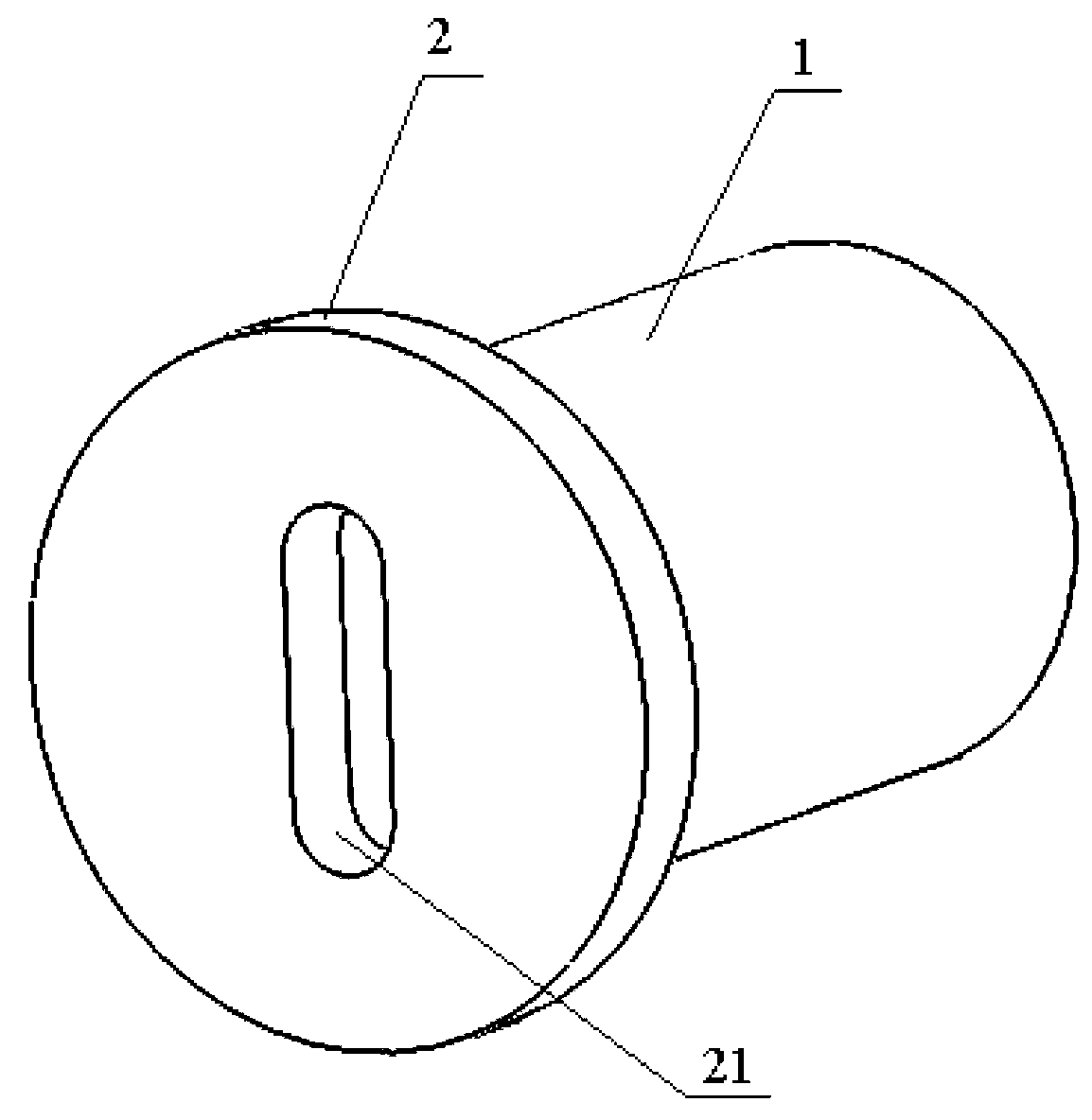
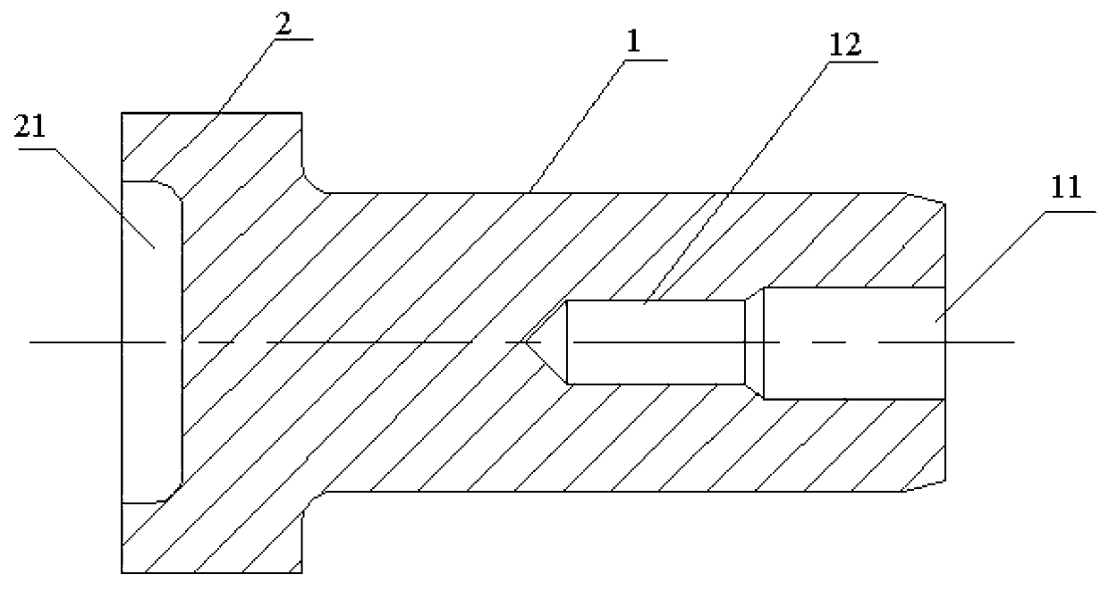
[0027] The anti-cracking processing method of the small shaft surface carburized and quenched stepped shaft with grooves on the end surface. In this embodiment, the stepped shaft to be manufactured is as follows figure 1 and figure 2 As shown, the stepped shaft includes two shaft segments: a thinner shaft segment A and a thicker shaft segment B, where the shaft segment A and the shaft segment B are connected to form a step. Among them, the length of shaft section A is required to be 55.295 mm to 55.3 mm, the total length of the shaft is required to be 59.9 mm to 60.1 mm, and the length of shaft section B is jointly limited by the total length of the shaft and the length of shaft section A. The diameter of shaft section A is required to be 35.959mm to 35.975mm, and the diameter of shaft section B is required to be 48.8mm to 49mm. The outer end surface of the shaft section A requires a center hole 11 of φ14×15, and a threaded hole 12 with a specification of M12×35 is required ...

Embodiment 2~5

[0039] The size of the protective steps and the effect after quenching in Examples 2-5 are as follows: (except for the different protective steps, the rest of the process parameters are the same)

[0040]

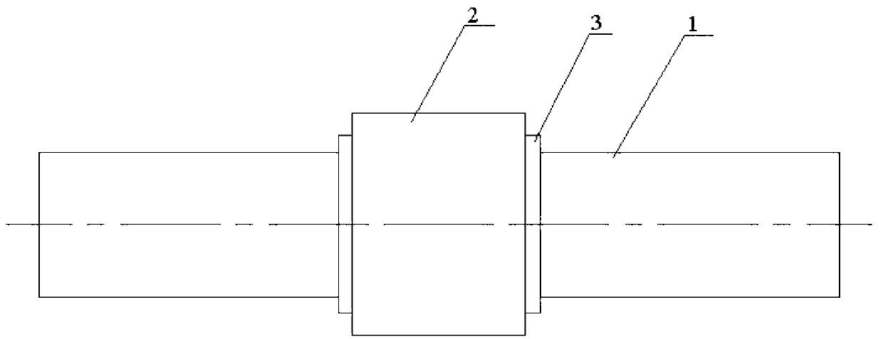
[0041] It can be seen from the above table that the setting of the protective step can effectively prevent the occurrence of cracks on the end face of the step and improve the qualified rate of finished products; when the width and height of the protective step are 0.7 to 1 times the depth of the carburized layer, it can Form a relatively shallow carburized layer with low carbon content, so that the root of the step still has a certain hardness and wear resistance after quenching; when the width and height of the protective step are 1 to 3 times the depth of the carburized layer At the same time, there will be no carburized layer at the root of the step, so the stress is small, the possibility of cracks is low, and the product qualification rate is high; in production, th...


PUM

PropertyMeasurementUnit
lengthaaaaaaaaaa
diameteraaaaaaaaaa
diameteraaaaaaaaaa

Abstract

The invention discloses an anti-cracking machining method of a small axial surface carburizing and hardening stepped shaft with an end face provided with a groove. The groove is arranged in an end face of a shaft section B of the stepped shaft, a shaft section A and a side face, close to the shaft section A, of the shaft section B have carburizing and hardening requirements, other parts have no hardness requirements, 20Cr steel serves as blanks of the stepped shaft, the procedures of blanking, rough machining, carburizing treatment, semi finish machining, hardening, fine machining, cutting and groove milling are sequentially carried out on the blanks, and then the stepped shaft with different shaft sections having different mechanical properties are machined. The anti-cracking machining method is simple in structure and convenient to achieve; a protective step is arranged before carburizing, the protective step before the hardening is machined to be a fillet, and cracking caused by oversize stress when the carburizing and hardening are carried out on the root portion of the step can be effectively avoided; a shaft section B carburized layer is milled off before the hardening, the hardness of the shaft section B after the hardening is reduced, and machining efficiency of following steps is improved.

Description

technical field [0001] The invention relates to the field of mechanical processing, in particular to a processing method for a stepped shaft that can avoid cracks at the steps. Background technique [0002] A shaft is a mechanical part that supports and revolves with a rotating part to transmit motion, torque or bending moment. Common shafts are generally processed according to the procedures of blanking, rough turning, quenching and tempering, finishing turning, grinding, inspection and warehousing. Some shafts need to be assembled with different rotating parts at different positions. Therefore, in order to facilitate positioning and save costs, different sections of the shaft can be designed with different diameters to meet the needs of assembly and torque transmission. Because there are steps between the sections of this shaft, it is generally called a stepped shaft or a stepped shaft. [0003] For some occasions with high load and high speed, conventional shafts cannot...

Claims


Application Information

Patent Timeline
Patent Type & Authority Applications(China)
IPC IPC(8): B23P15/14
Inventor 张之涛程景龙刘良华李建新张淑敏
Owner HEBEI HUABEI DIESEL ENGINE
Learn More