Yaw brake of wind power generation device and controlling method thereof

A technology for wind power generation equipment and yaw brakes, which is applied to the types of brakes, axial brakes, mechanical equipment, etc., can solve problems such as fan out of control, failure to brake, and no mention of the improvement of hydraulic loading cylinder oil leakage. Achieve the effect of reducing working pressure and prolonging service life

Inactive Publication Date: 2013-10-09
DALIAN HUARUI HEAVY IND GRP CO LTD
View PDF12 Cites 17 Cited by
  • Summary
  • Abstract
  • Description
  • Claims
  • Application Information

AI Technical Summary

Problems solved by technology

[0006] 1. "A Wind Turbine Pin Hole Plug-in Yaw Brake Device" (Patent No.: 200610012287.5) provides a plug-in yaw brake device that uses mechanical limit to realize the braking function. This pin hole The plug-in yaw brake device needs to process multiple conical pin holes on the brake disc, the processing technology is complicated, and the conical pins are easy to cause mechanical damage to the surface near the conical hole of the brake disc during long-term operation
[0007] 2. "Adjustable Wind Turbine Yaw Brake" (Patent No.: 200810203274.5), using symmetrically arranged adjustable brake calipers to realize the yaw brake function of the wind turbine, due to structural limitations, the space size of the yaw brake is too large to be able to Widely used in existing wind turbines
[0008] 3. "Wind Turbine Yaw Brake Device" (Patent No.: 200920028638.0) adopts the most commonly used traditional pure hydraulic loading type at present. The sealing ring is easy to be damaged during long-term work, and the hydraulic system failure or power failure of the power grid Yaw damping cannot be provided under this condition, which may easily cause the wind turbine to run out of control and cause danger
[0009] 4. "Yaw Brake" (Patent No.: 200920224175.5), adopts hydraulic loading type, and adds a guide belt to the oil cylinder to prolong the service life of the sealing ring. The disadvantage is that the brake cannot continue to provide power when the hydraulic system fails or the power grid fails. Damping, easy to cause the fan to run out of control and cause danger
[0010] 5. "A wind turbine yaw braking system" (patent number: 201020205838.1), which improves the problem that the existing equipment cannot provide damping in the case of power failure, and adopts n normally open hydraulically loaded yaw The disadvantage of the combination of navigation brakes and m normally closed spring-loaded yaw brakes is that the two types of yaw brakes need to be controlled separately, the number of brakes is large, the assembly difficulty is increased, and the installation interface of the main engine needs to be modified
[0011] 6. Each brake caliper of "Yaw Brake" (Patent No.: 201020580057.0) is equipped with 3 oil cylinders, two of which are hydraulically loaded, and the other is spring-loaded. The two types work alternately or simultaneously to achieve yaw with different needs Braking, the disadvantage is that the spring loading capacity is limited, and the area of ​​the friction plate is small, which cannot meet the demand for large yaw braking torque
[0012] 7. "Yaw Brakes for Wind Turbine Generators" (Patent No.: 201220056396.8) has made certain improvements to the traditional hydraulically loaded yaw brakes, mainly by adding a brake pad return spring, but for this type of yaw brakes often The problem of easy oil leakage and the problem of not being able to brake in an emergency have not been improved
[0013] 8. "Wind Turbine Yaw Brake" (patent number: 201220215704.7), in order to solve the problem that traditional yaw brakes cannot provide damping in emergency situations, the three oil cylinders of the brake caliper are divided into two types, two oil cylinders Hydraulic loading is still used, and the other cylinder is spring-loaded. The two are used separately or in combination. The disadvantage is that because there is only one spring-loaded cylinder, the torque provided is limited and cannot meet the demand for large yaw braking torque. In addition, the design No mention of improvements to hydraulically loaded cylinders leaking

Method used


Image

  • Yaw brake of wind power generation device and controlling method thereof
  • Yaw brake of wind power generation device and controlling method thereof
  • Yaw brake of wind power generation device and controlling method thereof

Examples


Embodiment Construction

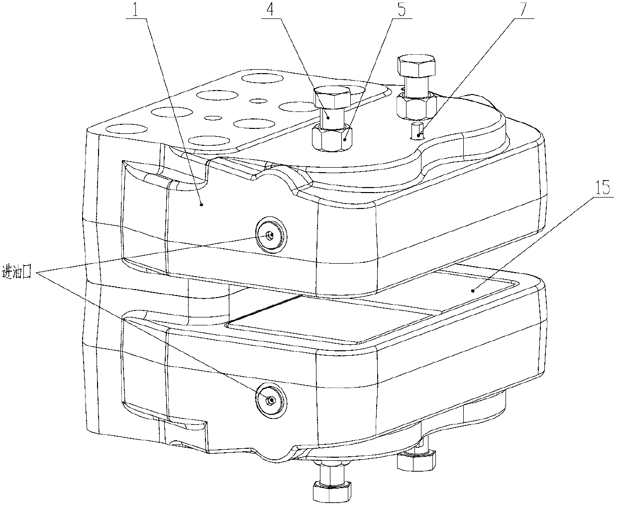
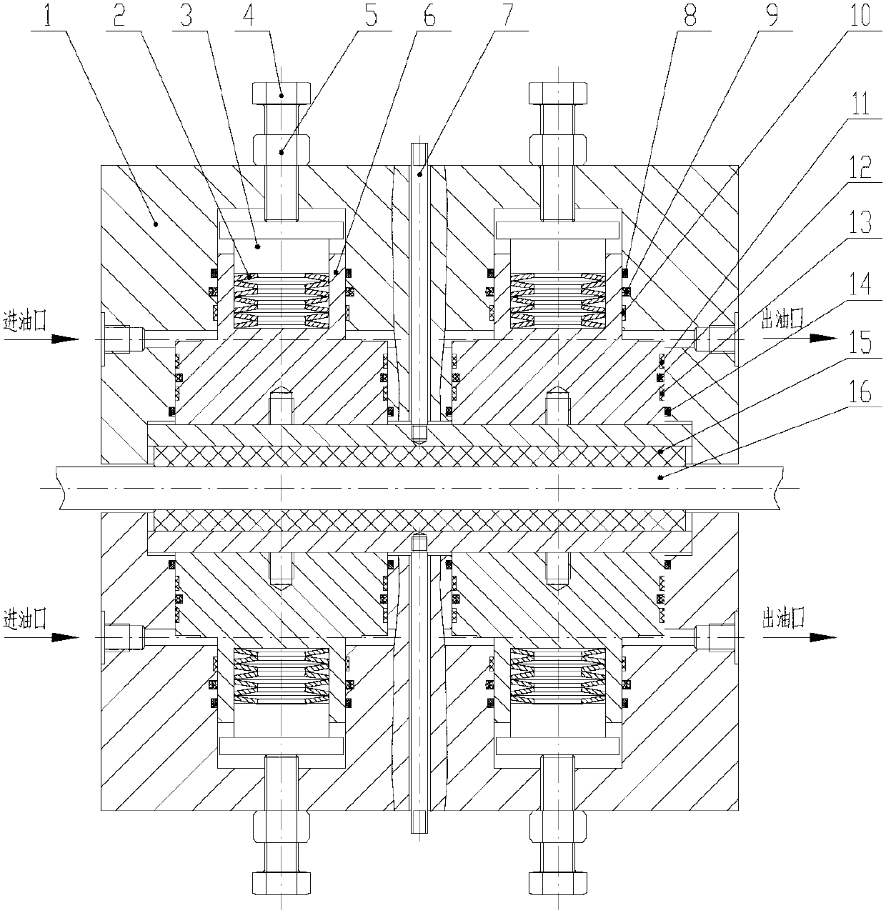
[0039] The present invention will be further described below in conjunction with the accompanying drawings. Such as Figure 1-3 As shown, a yaw brake for wind power generation equipment includes two brake calipers with identical structures, and the two brake calipers are symmetrically installed on the upper and lower sides of the brake disc 16 through eight high-strength bolt connections; The brake caliper has a left-right symmetrical structure, including brake bracket 1, disc spring group 2, guide block 3, adjusting bolt 4, lock nut 5, piston 6, wear indicator 7, dust-proof ring A8, high-pressure sealing ring A9 , guide belt A10, guide belt B11, high-pressure sealing ring B12, guide belt C13 and dust-proof ring B14, two oil cylinders are processed on the brake bracket 1, a piston 6 is installed in the oil cylinder, and a piston 6 is provided with an installation The counterbore of the disc spring group 2, the disc spring group 2 is compressed and installed in the counterbore...


PUM


Abstract

The invention discloses a yaw brake of a wind power generation device and a controlling method of the yaw brake of the wind power generation device. The yaw brake comprises two brake calipers which are completely same with each other in structure, and the two brake calipers are connected to the left side of a brake disc and the right side of the brake disc respectively in a symmetrical mode through eight high-intensity bolts. Each brake caliper is of a bilateral symmetrical structure, and comprises a brake support, a disc spring set, a guiding block, an adjusting bolt, a locking nut, a piston, an abrasion indicator, a dustproof ring A, a high-pressure sealed ring A, a guiding belt A, a guiding belt B, a high-pressure sealed ring B, a guiding belt C and a dustproof ring B. According to the yaw brake of the wind power generation device, a disc spring hydraulic combined loading mode is adopted, no hydraulic system needs to provide pressure during the yaw process of a fan, the yaw brake force is generated only through the loading of the disc spring force, and a sealing device is prevented from bearing the action of the hydraulic pressure and the tangential force at the same time and being damaged during the yaw process. Multiple sets of guiding belts are adopted, the oil leakage problem is solved, working pressure of a hydraulic controlling system is reduced, and the service life of the sealing device can be effectively prolonged.

Description

technical field [0001] The invention relates to a yaw brake system related to wind power generating equipment, in particular to a yaw brake of wind power generating equipment and a control method thereof. Background technique [0002] The yaw system is one of the essential components of the horizontal axis wind turbine. It has two main functions: one is to make the wind turbine always be in the windward state with the change of the wind direction, make full use of wind energy and improve the power generation efficiency; The second is to provide the necessary braking torque to ensure the safe operation of the wind turbine. [0003] The yaw brake is the main component in the yaw braking system. When the wind turbine is running normally, the yaw brake provides sufficient braking force to hold the nacelle in a specific position; when it needs to yaw, the yaw brake provides a small braking force so that the nacelle can smoothly rotate around the vertical axis turn. [0004] Ex...

Claims


Application Information

Patent Timeline
Patent Type & Authority Applications(China)
IPC IPC(8): F16D55/226F16D65/14F16D121/04F16D121/14F16D125/02
Inventor 董连俊宋玉涛陈强史显忠杨京兰
Owner DALIAN HUARUI HEAVY IND GRP CO LTD
Why Eureka
Try Eureka