Double-pre-film pneumatic nebulization low pollution combustor head structure
A technology of pneumatic atomization and combustion chamber, which is applied in the direction of combustion chamber, continuous combustion chamber, combustion method, etc., to achieve the effect of reducing pollution emissions
- Summary
- Abstract
- Description
- Claims
- Application Information
AI Technical Summary
Problems solved by technology
Method used
Image
Examples
Embodiment Construction
[0031] The present invention will be further described below in conjunction with the accompanying drawings and specific embodiments.
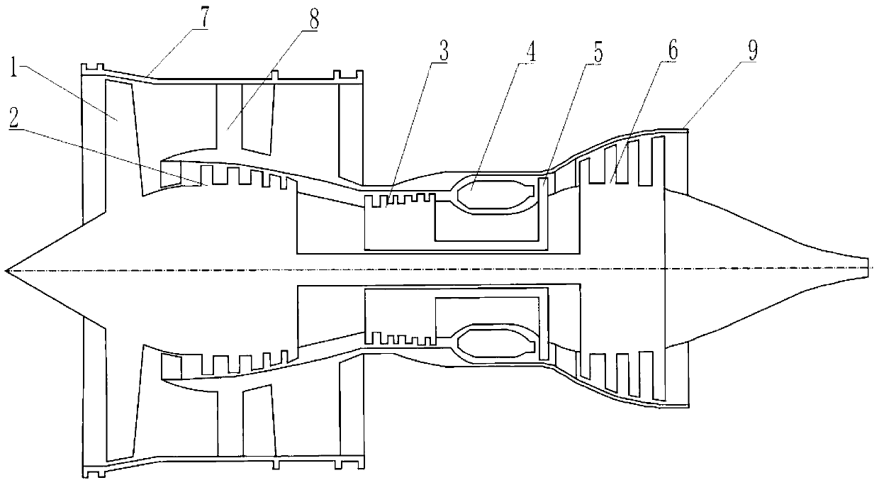
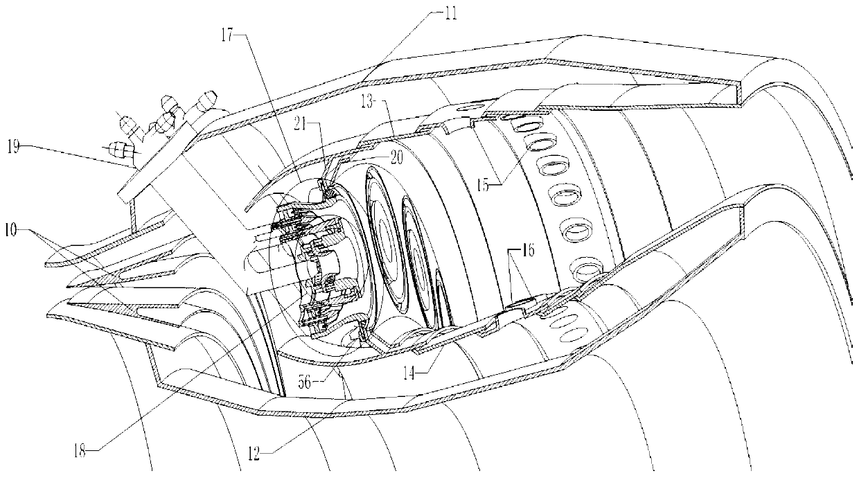
[0032] figure 1 It is a schematic diagram of the engine structure; including a fan 1, a low-pressure compressor 2, a high-pressure compressor 3, a combustion chamber 4, a high-pressure turbine 5, a low-pressure turbine 6, a fan casing 7, guide vanes 8, and an engine outer casing 9. When the engine is working, after the air is compressed by the fan 1, part of the air is discharged through the external duct, and part of it enters the low-pressure compressor 2 for further compression, and then enters the high-pressure compressor 3. The high-temperature and high-pressure air then enters the combustion chamber 4 to burn with fuel, and after combustion The formed high-temperature and high-pressure gas enters the high-pressure turbine 5 and the low-pressure turbine 6, and drives the high-pressure compressor 3, low-pressure compressor 2 and fan 1 respe...
PUM
| Property | Measurement | Unit |
|---|---|---|
| Thickness | aaaaa | aaaaa |
Abstract
Description
Claims
Application Information
 - R&D
- Intellectual Property
- Life Sciences
- Materials
- Tech Scout
- Unparalleled Data Quality
- Higher Quality Content
- 60% Fewer Hallucinations
Browse by: Latest US Patents, China's latest patents, Technical Efficacy Thesaurus, Application Domain, Technology Topic, Popular Technical Reports.
© 2025 PatSnap. All rights reserved.Legal|Privacy policy|Modern Slavery Act Transparency Statement|Sitemap|About US| Contact US: help@patsnap.com


