Metallization power capacitor rapid aging testing device

A technology of power capacitor and test device, applied in the field of power electronics, can solve the problems of high cost, poor safety, long test period and the like

Active Publication Date: 2013-10-09
指月集团有限公司
View PDF12 Cites 5 Cited by
  • Summary
  • Abstract
  • Description
  • Claims
  • Application Information

AI Technical Summary

Problems solved by technology

[0006] The technical problem to be solved by the present invention is that the capacitor aging test device in the prior art has complex structure, poor safety, long test period, high cost

Method used


Image

  • Metallization power capacitor rapid aging testing device
  • Metallization power capacitor rapid aging testing device
  • Metallization power capacitor rapid aging testing device

Examples


Embodiment 1

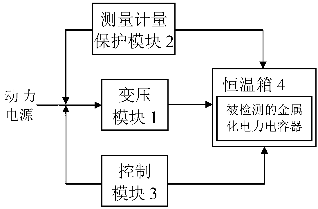
[0047] The structure of the metallized power capacitor rapid aging test device of the present invention is as follows figure 1 As shown, it includes a transformer module 1 , a measurement and protection module 2 , a control module 3 , and a constant temperature box 4 .

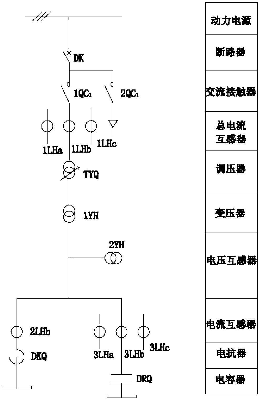
[0048] The voltage transformation module 1 is used to increase the voltage of the power supply to the voltage value required by the test voltage. The voltage transformation module 1 includes a voltage regulator TYQ and a transformer 1YH; the primary side of the voltage regulator TYQ is connected to the AC contactor 1QC conversion contact 1QC 1 The common contact of the voltage regulator TYQ is connected to the primary side of the transformer 1YH, and the secondary side of the transformer 1YH is connected to the detected metallized power capacitor.

[0049] The measurement measurement protection module 2 includes a test time measurement unit, an access voltage measurement unit, a capacitor voltage measurement ...

Embodiment 2

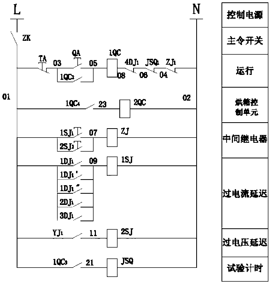
[0065] On the basis of the above embodiments, the control module further includes a work instruction unit. Such as Figure 9 As shown, the work indication unit includes signal lights 1XD, 2XD, 3XD, and the AC contactor 1QC conversion contact 1QC 5 , the AC contactor 2QC changeover contact 2QC 2 ; One end of the signal lamp 1XD is connected to the positive pole of the control power supply, the other end of the signal lamp 1XD is connected to the negative pole of the control power supply, and the AC contactor 1QC conversion contact 1QC 5 The common contact of the control power supply is connected to the positive pole of the control power supply, and the AC contactor 1QC transfer contact 1QC 5 The normally open contact of the signal lamp 2XD is connected to one end of the signal lamp 2XD, the other end of the signal lamp 2XD is connected to the negative pole of the control power supply, and the AC contactor 2QC conversion contact 2QC 2 The common contact of the control power s...

Embodiment 3

[0067] On the basis of the above embodiments, the measurement protection module further includes a display unit for overcurrent, short circuit current and overvoltage signals. Such as Figure 10 As shown, the display unit of the overcurrent, short circuit current and overvoltage signal includes signal relays 1XJ, 2XJ, 3XJ, 4XJ, current relay 1DJ changeover contact 1DJ 2 , Current relay 1DJ' changeover contact 1DJ 2 ', current relay 1DJ "changeover contact 1DJ 2 ", current relay 2DJ changeover contact 2DJ 2 , current relay 3DJ changeover contact 3DJ 2 , Voltage relay YJ changeover contact YJ 2 ; The current relay 1DJ changeover contact 1DJ 2 , The current relay 1DJ' changeover contact 1DJ 2 ', the current relay 1DJ "changeover contact 1DJ 2 "The public contact of "is connected with the public contact of said master switch ZK, and said current relay 1DJ changeover contact 1DJ 2 , The current relay 1DJ' changeover contact 1DJ 2 ', the current relay 1DJ "changeover contac...


PUM


Abstract

The invention relates to a metallization power capacitor rapid aging testing device which comprises a voltage transformation module, a measurement metering protection module, a constant temperature box and a control module. The voltage transformation module is used for improving power supply voltage to a voltage value needed by voltage testing. The measurement metering protection module is used for achieving testing time metering, input voltage measurement, total current measurement, electric reactor current measurement, capacitor current measurement and capacitor voltage measurement, and used for carrying out delay protection and short-circuit instantaneous protection on overvoltage and an overcurrent. The constant temperature box is used for providing a constant temperature environment in a testing process, and a metallization power capacitor to be tested is arranged in the constant temperature box. The control module is used for controlling stating and stopping of the whole testing device and operation of the constant temperature box. The metallization power capacitor rapid aging testing device effectively resolves the problems that in the prior art, a capacitor aging testing device is complex in structure, poor in safety, long in testing cycle, and high in cost and energy consumption.

Description

technical field [0001] The invention relates to a capacitor aging test device, in particular to a metallized power capacitor rapid aging test device and a test method thereof, belonging to the technical field of power electronics. Background technique [0002] With the rapid development of the national economy and the increasing demand for electricity, the country will vigorously promote the construction of a strong smart grid, and at the same time drive the rapid development of the electrical instrumentation industry. As an indispensable instrument in a strong smart grid, smart power electronic instruments continue to expand their market share with their unique functions. The development of a strong smart grid urgently requires the development of new products, and metallized power capacitors are widely cited as important devices in smart grids. [0003] Metallized power capacitor is a kind of metallized film capacitor. It uses polypropylene electrical film as the medium, a...

Claims


Application Information

Patent Timeline
IPC IPC(8): G01R31/00
Inventor 陈麟玲
Owner 指月集团有限公司
Why Eureka
Try Eureka