LED transient thermal resistance measuring system

A measurement system and transient thermal resistance technology, applied in the field of LED thermal resistance transient measurement system, can solve problems such as large test error, limited in-depth analysis of thermal problems, and inability to measure non-destructive devices, achieving fast measurement time and accurate measurement results. , the effect of a large temperature controllable range

Active Publication Date: 2013-10-09
SHANGHAI UNIV
View PDF7 Cites 17 Cited by
  • Summary
  • Abstract
  • Description
  • Claims
  • Application Information

AI Technical Summary

Problems solved by technology

The main disadvantage of the infrared thermal imaging method is that it can only measure unpackaged bare chips, and cannot achieve non-destructive measurement of packaged devices. relatively large error
However, the electrical parameter method can only provide the average value of the junction temperature of the device and the overall thermal resistance, but cannot provide the thermal resistance of each component. There are still deficiencies in the thermal analysis of the interface, which limits the in-depth analysis of thermal problems.
Spectrum and optical power methods also have their limitations

Method used


Image

  • LED transient thermal resistance measuring system
  • LED transient thermal resistance measuring system
  • LED transient thermal resistance measuring system

Examples


Embodiment 1

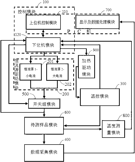
[0027] see figure 1 : This LED transient thermal resistance measurement system includes: a control module (100), a constant current source drive module (200), a temperature control module (300), a data acquisition module (400), a switch group module (500), a test The sample module (600), the display and data processing module (700), the temperature measurement module (800) and the heating drive module (900), are characterized in that: with the control module (100) as the center, the constant current source drive module is connected and controlled (200), heating drive module (900) and switch group module (500); The constant current source drive module (200) receives the PWM control signal from the control module (100), and it is output to the constant current of the sample module to be tested (600). The flow is controlled by the switch group module (500) connected to it; the state of the switch group module (500) is determined by the control module (100) connected to it, and ou...

Embodiment 2

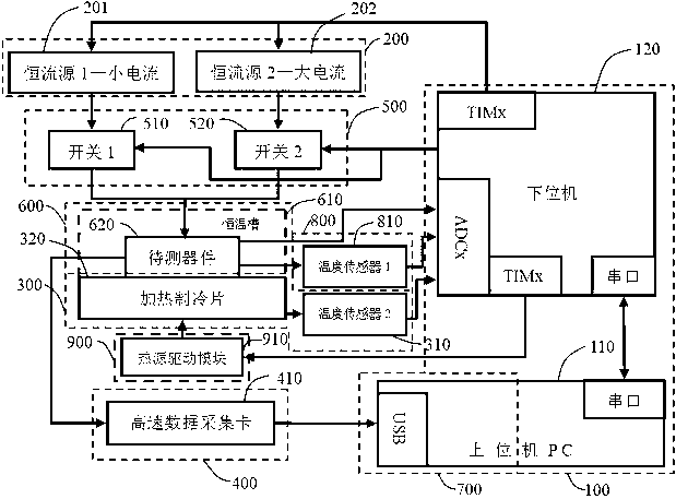
[0029] see figure 1 and figure 2 , the present embodiment is basically the same as Embodiment 1, and the special features are as follows: the control module (100) is composed of a host computer (110) connected to a lower computer (120); through the upper computer (110), the relevant parameters are determined. Setting, data communication between the upper and lower computers through the serial port, the upper computer (110) transmits the parameters to the lower computer (120), and the lower computer (120) according to the relevant parameters and the temperature control module (300) and the switch group module (500) feedback signal, output PWM signal to constant current source drive module (200), heating drive module (900) and output switch control signal; lower computer (100) receives from constant current source drive module (200) and temperature control Feedback signal of the module (300). The input end of the constant current source drive module (200) is connected with th...

Embodiment 3

[0031] To obtain a measurement of the transient thermal resistance of the LED, figure 1 and figure 2 The structural diagram of the measurement system of the preferred embodiment of the transient thermal resistance of the LED is given.

[0032] see figure 1 , the system mainly consists of a control module (100), a constant current source drive module (200), a temperature control module (300), a data acquisition module (400), a switch group module (500), a sample module to be tested (600), a display And a data processing module (700), a temperature measurement module (800) and a heating driving module (900). See details figure 1 and figure 2 , in a preferred embodiment of the present invention, the control module (100) mainly consists of a host computer (110) and a lower computer (120); the constant current source drive module (200) mainly includes a constant current source 1-small current (201) , constant current source 2-high current (202); the temperature control modul...


PUM


Abstract

The invention relates to an LED transient thermal resistance measuring system which can realize measurement of LED transient thermal resistance. The LED transient thermal resistance measuring system comprises a control module, a constant current source driving module, a switching group module, a temperature control module, a sample-to-be-tested module, a temperature measurement module, a data acquisition module and a display and data processing module. Through the mode that an upper computer PC is combined with a lower computer, the LED transient thermal resistance measuring system realizes real-time control over signals, setting of relevant parameters and final data processing and analysis, thereby being capable of realizing accurate measurement of the LED transient thermal resistance.

Description

technical field [0001] The invention relates to a LED thermal resistance transient measurement system, which is used for measuring the LED transient thermal resistance. technical background [0002] Solid-state lighting is considered to be one of the most promising lighting sources in the 21st century. Due to the advantages of small size, long life, energy saving and environmental protection, high luminous efficiency, pure chromaticity and high reliability, light-emitting diodes (LEDs) have been widely used in It will play an increasingly important role in indoor and outdoor daily lighting. [0003] However, the increase of the working current of the power LED will generate a lot of heat, which will cause a significant change in the PN junction temperature of the LED chip, which will have an important impact on the performance of the LED, resulting in changes in the forward voltage drop, color temperature changes, wavelength red shift, and photoelectric conversion. The effi...

Claims


Application Information

Patent Timeline
Patent Type & Authority Applications(China)
IPC IPC(8): G01R31/26
Inventor 张建华陈伟黄元昊杨连乔
Owner SHANGHAI UNIV
Why Eureka
Try Eureka