Shunt active power filter
A power filter, filter technology, applied in active power filter, AC network to reduce harmonics/ripples and other directions, can solve the problem of zero-sequence potential imbalance, electromagnetic interference, etc., to prevent interference, high anti-interference sexual effect
- Summary
- Abstract
- Description
- Claims
- Application Information
AI Technical Summary
Problems solved by technology
Method used
Image
Examples
Embodiment 1
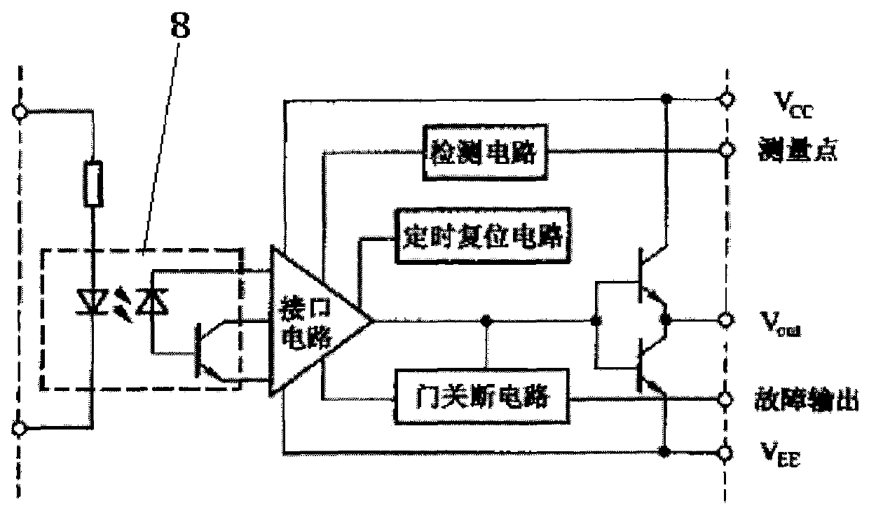
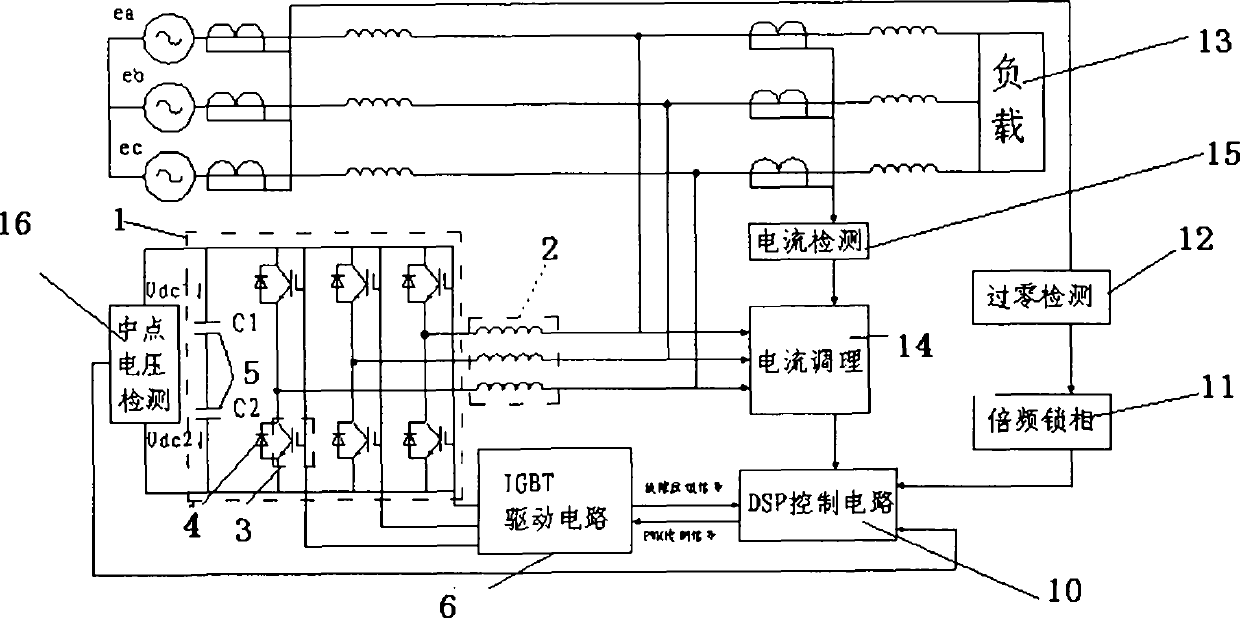
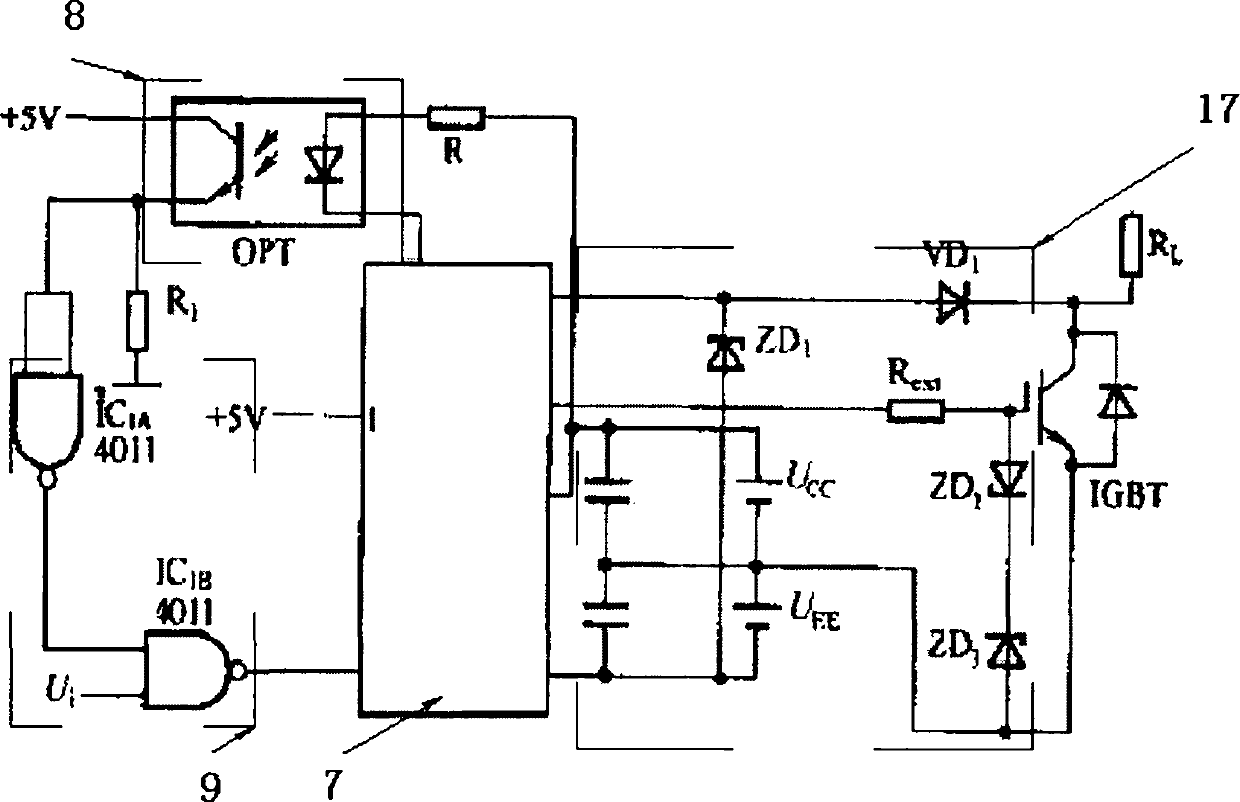
[0029] A shunt active power filter, such as Figure 1-3 As shown, the three-level inverter 1 is connected to six IGBT drive circuits 6, the IGBT drive circuit 6 is connected to the DSP control circuit 10, and the DSP control circuit 10 is connected to the load through the frequency multiplication phase-locking device 11 and the zero-crossing detection device 12. 13, and the other path of the DSP control circuit 10 is connected to the load 13 through the current conditioning device 14 and the current detection device 15, the current conditioning device 14 is connected to the three-level inverter 1 through the filter 2, and the filter 2 is also connected to the load 13 The three-level inverter 1 is provided with a clamping diode 4 , a switch tube 3 and a voltage dividing capacitor 5 connected in sequence, and the DSP control circuit 10 is connected to the three-level inverter 1 through a midpoint voltage detection device 16 .
[0030] The structure of the IGBT driving circuit is...
Embodiment 2
[0058] A shunt active power filter, such as Figure 1-3 As shown, the three-level inverter 1 is connected to six IGBT drive circuits 6, the IGBT drive circuit 6 is connected to the DSP control circuit 10, and the DSP control circuit 10 is connected to the load through the frequency multiplication phase-locking device 11 and the zero-crossing detection device 12. 13, and the other path of the DSP control circuit 10 is connected to the load 13 through the current conditioning device 14 and the current detection device 15, the current conditioning device 14 is connected to the three-level inverter 1 through the filter 2, and the filter 2 is also connected to the load 13 The three-level inverter 1 is provided with a clamping diode 4 , a switch tube 3 and a voltage dividing capacitor 5 connected in sequence, and the DSP control circuit 10 is connected to the three-level inverter 1 through a midpoint voltage detection device 16 .
[0059] The structure of the IGBT driving circuit is...
PUM
 Abstract
Description
Claims
Application Information
 - R&D
- Intellectual Property
- Life Sciences
- Materials
- Tech Scout
- Unparalleled Data Quality
- Higher Quality Content
- 60% Fewer Hallucinations
Browse by: Latest US Patents, China's latest patents, Technical Efficacy Thesaurus, Application Domain, Technology Topic, Popular Technical Reports.
© 2025 PatSnap. All rights reserved.Legal|Privacy policy|Modern Slavery Act Transparency Statement|Sitemap|About US| Contact US: help@patsnap.com


