Chained ditcher

A ditching machine and chain-type technology, applied in the direction of digging/covering ditches, planting methods, earth movers/shovels, etc., can solve the difficulty of repairing and replacing earth shovels, the inability to automate ditching, and the inconvenience of installation, etc. problems, to achieve the effect of improving ditching efficiency, simple structure, and easy replacement

Inactive Publication Date: 2013-10-16
JIAXING VOCATIONAL TECHN COLLEGE
View PDF8 Cites 10 Cited by
  • Summary
  • Abstract
  • Description
  • Claims
  • Application Information

AI Technical Summary

Problems solved by technology

[0004] However, the above-mentioned chain type ditching device has the following disadvantages: 1. When adjusting the depth, width and direction of soil discharge of the ditch, it needs to be adjusted by increasing or decreasing the number of chain rows, which is inconvenient to operate; 2. The ditching machine belongs to Mechanized operation cannot carry out automatic ditching, and the efficiency is low; 3. Difficult to maintain and replace the shovel, and inconvenient to install; 4. The structure is more complicated

Method used


Image

  • Chained ditcher
  • Chained ditcher

Examples


Embodiment 1

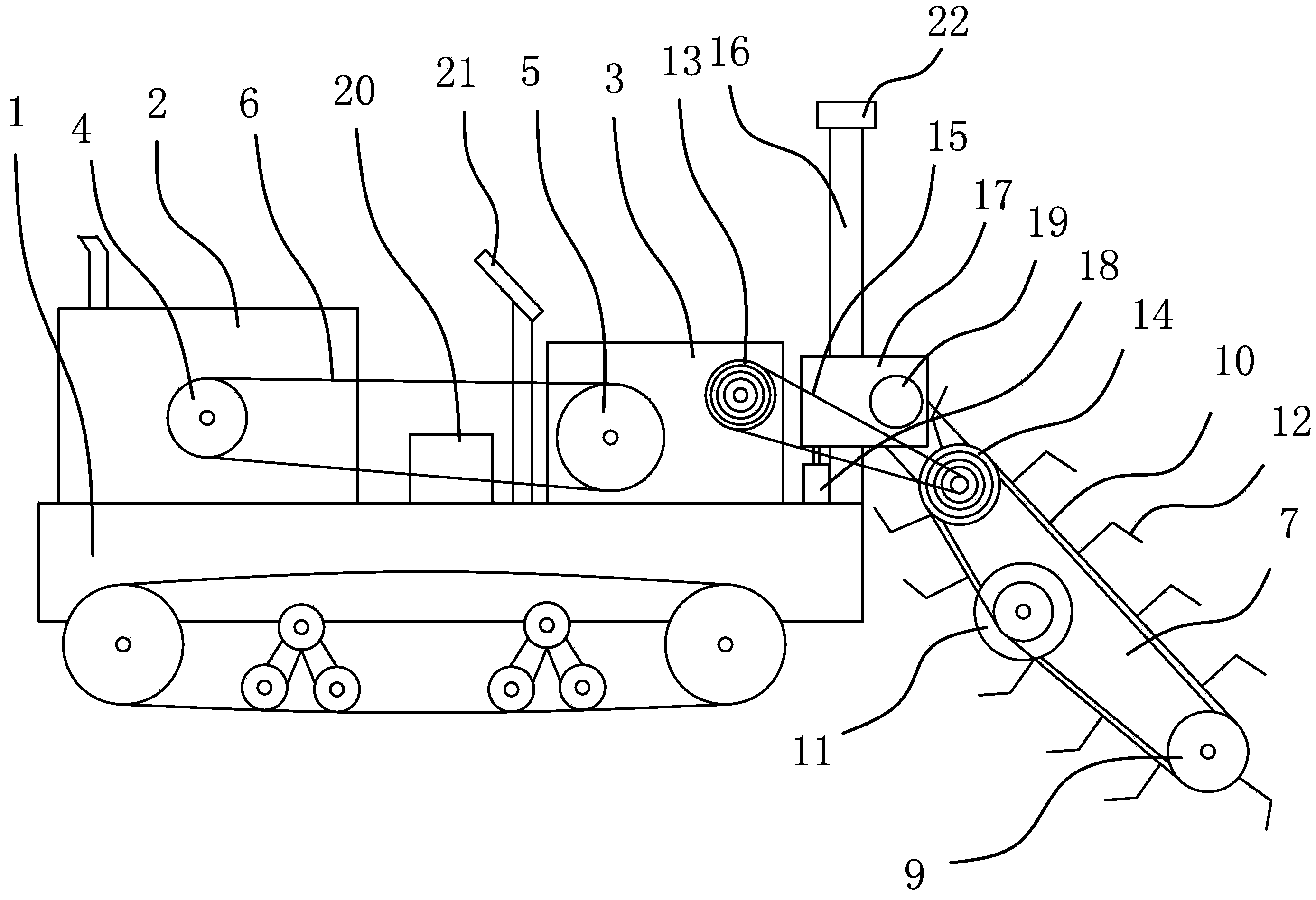
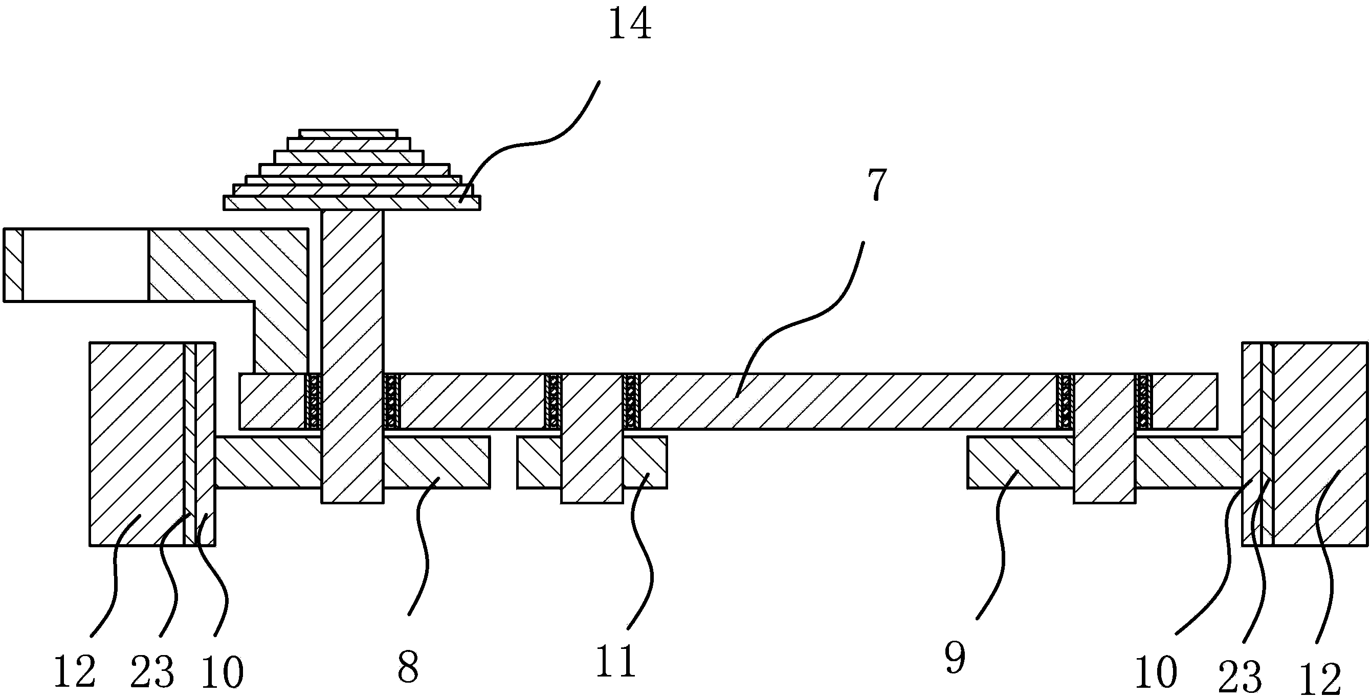
[0027] Such as figure 1 Shown, a kind of chain ditching machine comprises body 1, is fixed with diesel engine 2 and speed reducer 3 on body 1, and diesel engine 2 has output shaft, and belt pulley-4 is fixed on the output shaft, and speed reducer 3 has power input shaft and The power output shaft and the power input shaft are fixed with pulley 2 5, pulley 1 4 and pulley 2 5 are in the same plane, and pulley 1 4 and pulley 2 5 are connected through V-belt 6; figure 2As shown, one side of the body 1 is provided with a ditching device capable of digging ditches to the land, including a support 7, a driving sprocket 8, a driven sprocket 9, a chain 10, a stirring wheel 11 and some chain knives 12, The driving sprocket 8 is axially positioned on one end of the support 7 through the rotating shaft one, the driven sprocket 9 is axially positioned on the other end of the support 7 through the rotating shaft two, and the stirring wheel 11 is axially positioned on the support 7 through ...

Embodiment 2

[0037] The structure and principle of this embodiment are basically the same as the first embodiment, the difference is: in the first embodiment, the lifting and positioning mechanism is a cylinder 18; and in the second embodiment, the lifting and positioning mechanism is a push rod motor , the push rod motor is vertically arranged, and the push rod motor is fixed on the body 1 by screws, the push rod of the push rod motor is vertically upward, and the upper end of the push rod is fixed on the lower side of the slide block 17. The push rod motor is connected to the PLC programmable controller 20 on the body 1 through a line, and the push rod motor is started, and the push rod of the push rod motor can be stretched up and down, thereby pushing the sliding block 17 up and down along the column 16, and finally the sliding block 17 moves up and down with the bracket 7 on one side of the body 1; when the bracket 7 moves to a reasonable height, turn off the push rod motor to position...


PUM


Abstract

The invention provides a chained ditcher, belongs to the technical field of agricultural machinery, and solves the problems that in a conventional chained ditcher, a chain tool cannot be lifted up and down, and the degree of automation is low. The chained ditcher comprises a body, a diesel engine and a speed reducer are fixed on the body, a ditching device is arranged on one side of the body, and comprises a bracket, a drive chain wheel, a driven chain wheel, a chain I, a reel and a plurality of chain tools, wherein the drive chain wheel, the driven chain wheel and the reel are respectively and axially positioned on the bracket through a rotating shaft, the reel is positioned between the drive chain wheel and the driven chain wheel, the chain I acts on the drive chain wheel, the driven chain wheel and the reel at the same time, the chain tools are uniformly arranged on the outer side of the chain I, a column is also fixed on the body, a sliding block is sheathed on the column, one end of the bracket is hinged to the sliding block, and a lifting positioning mechanism, which can cause the sliding block to move up and down along the column and position the sliding block on the column, is arranged between the body and the sliding block. The chain tools in the chained ditcher can be lifted up and down, and the degree of automation is high.

Description

technical field [0001] The invention belongs to the technical field of agricultural machinery and relates to a chain ditching machine. Background technique [0002] In recent years, with the adjustment of the agricultural industrial structure and the state's attention to the issues of agriculture, rural areas and farmers, as well as the increase in investment in agriculture, farmers' enthusiasm for planting cash crops has increased significantly. With the improvement of people's living standards, the demand for fresh melons, fruits and vegetables is increasing, and the planting area is also increasing. In the planting and management of fruit, vegetable and rice fields, it is often necessary to dig drainage and irrigation ditches and fertilization ditches in the middle of the ground, and sometimes it is necessary to constantly change the position of the ditches to facilitate the normal growth of fruit trees, vegetables, rice and wheat and other crops. [0003] With the mecha...

Claims


Application Information

Patent Timeline
Patent Type & Authority Applications(China)
IPC IPC(8): A01C5/06
CPCE02B11/02E02F5/06
Inventor 王海峰闻敏杰
Owner JIAXING VOCATIONAL TECHN COLLEGE
Why Eureka
Try Eureka