Deflashing device for flange of wheel

A technology for deflashing and wheel rim removal, which is applied in the field of wheel rim deflashing devices, can solve the problems of waste products caused by blank cutting, influence of blank positioning accuracy, and low efficiency, so as to improve clamping positioning accuracy and processing efficiency, The effect of high degree of automation and advanced technology

Inactive Publication Date: 2013-10-16
CITIC DICASTAL
View PDF3 Cites 8 Cited by
  • Summary
  • Abstract
  • Description
  • Claims
  • Application Information

AI Technical Summary

Problems solved by technology

Among them, one rim flash has a certain impact on the positioning accuracy of the blank during machining; the second rim flash has a serious impact on the normal operation and detection accuracy of the subsequent X-ray

Method used


Image

  • Deflashing device for flange of wheel
  • Deflashing device for flange of wheel
  • Deflashing device for flange of wheel

Examples


Embodiment Construction

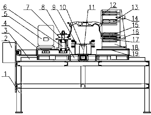
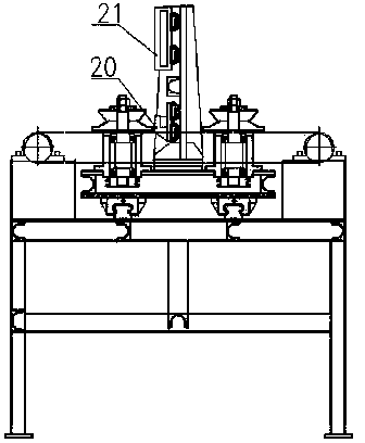
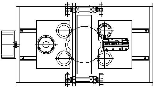
[0012] The details and working conditions of the specific device proposed according to the present invention will be described below in conjunction with the accompanying drawings.

[0013] The device consists of frame 1, clamping cylinder 2, guide rail A3, left sliding table 4, motor 5, clamping shaft 6, V-shaped block 7, rack 8, supporting plate 9, three-axis cylinder 10, gear 11, knife B12, guide rail B13, feed cylinder B14, guide rail C15, feed cylinder A16, knife A17, knife rest 18, right slide 19, knife holder A20 and knife holder B21, and two guide rails A3 are installed in parallel on frame 1 above, its sliders are connected with the left slide 4 and the right slide 19; The top of the slide table 4; the upper end is fixed with four clamping shafts 6 of the V-shaped block 7 respectively, and is installed on the inboard of the left slide table 4 and the right slide table 19, each two on the left and right sides. Racks 8 are respectively fixed under the left sliding table...


PUM


Abstract

The invention discloses a deflashing device for a flange of a wheel. The deflashing device comprises a rack, a cylinder, a motor, clamping shafts, a V-shaped block, a gear rack, a supporting plate, a gear, knives, a knife rest, knife holders and the like. When the wheel on a production line reaches the approximate middle position of four clamping shafts, a sensor enables the wheel to stop moving, and a three-axis cylinder lifts the wheel to the middle height of the V-shaped block through the supporting plate; a clamping cylinder pushes a left sliding table to move towards the middle, and a right sliding table moves towards the middle under the action of the gear rack of the gear, so that a wheel workblank is synchronously clamped in the V-shaped block and located in the central position; the motor drives two clamping shafts on the left side to rotate through a chain and drives the wheel to rotate in a clamping state through friction force; and under the action of feed cylinders, both the knife A and the knife B move forward, and relative cutting movement is formed when the knives are contacted with the flange, so that the flange can be well deflashed.

Description

technical field [0001] The invention relates to a deburring device, in particular to a wheel rim deburring device. Background technique [0002] In the low-pressure casting process of aluminum alloy wheel blanks, due to the long-term use of the mold, there will be a certain gap between the side molds. Produce irregular large flash. Among them, one wheel rim flash has a certain impact on the positioning accuracy of the blank during machining; the second wheel rim flash has a serious impact on the normal operation and detection accuracy of the subsequent X-ray machine. The traditional method of deflashing is that when the wheel blank is just demoulded, the worker holds a machete to cut it off. This method will cut the blank and cause waste if a little careless, and the efficiency is extremely low. In view of the above reasons, this device was invented, which not only can ensure the production of mixed lines, but also has extremely high efficiency. Contents of the invention...

Claims


Application Information

Patent Timeline
IPC IPC(8): B22D31/00
Inventor 薛博文郭建东刘伟东于志远刘会营葛磊任彦朝
Owner CITIC DICASTAL
Why Eureka
Try Eureka