
Design method of low mass flow velocity water circulation system for opposed firing boiler

A low-mass flow rate, circulation system technology, applied in the direction of boiler water pipes, etc., can solve the problems of increasing plant power consumption, high energy consumption, complex furnace structure, etc.

Inactive Publication Date: 2013-10-16
TRANSTEK IND HK LTD KOWLOON
View PDF4 Cites 4 Cited by
  • Summary
  • Abstract
  • Description
  • Claims
  • Application Information

AI Technical Summary

Problems solved by technology

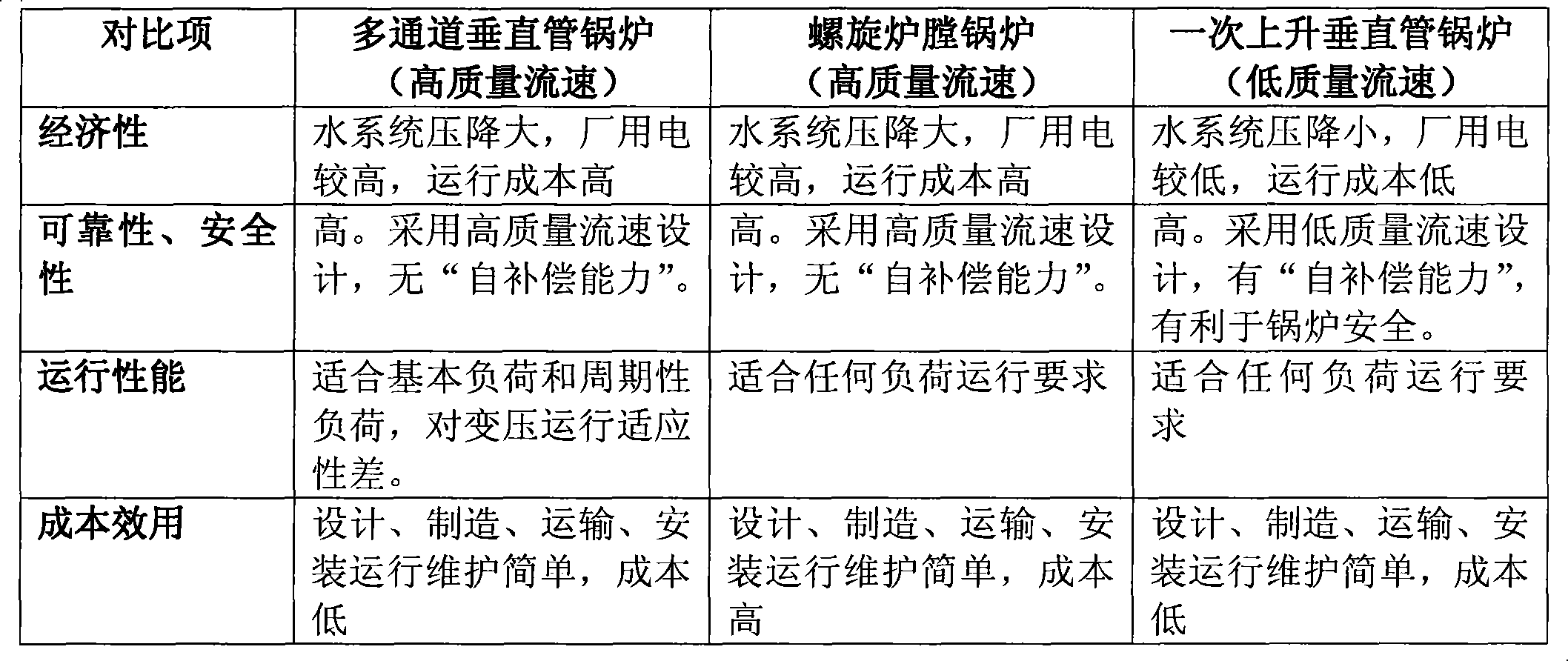
For the reciprocating rising multi-channel furnace design, when the load requires the boiler to operate below the supercritical pressure, the load adaptability is insufficient, and it is necessary to bear the throttling measures that must be taken to maintain the furnace above the supercritical pressure. The loss of power plant economic decline
Although the design of the spiral furnace avoids the lack of load adaptability of the above-mentioned multi-channel furnace design, but because the structure of the furnace is too complex, it causes difficulties and costs in a series of processes such as design, manufacture, transportation, installation and operation and maintenance. promotion
At the same time, both designs make the working medium in the water-cooled wall tube flow at an ultra-high velocity, which results in a substantial increase in the side pressure drop of the furnace working medium, which puts higher requirements on the pressure head of the feed water pump in the thermal cycle system of the power plant, increasing Increased plant power consumption
[0004] From the description in the previous section, it can be seen that there are insurmountable defects caused by their own structural characteristics in the two circulation system designs widely used in supercritical boilers at present, and these defects can only be overcome by adopting new technologies

Method used


Image

  • Design method of low mass flow velocity water circulation system for opposed firing boiler

Examples


Embodiment Construction

[0013] The present invention will be further described in detail below in conjunction with specific examples.

[0014] The present invention is a design method for the low-mass flow rate water circulation system of the opposed combustion boiler. The following measures must be adopted in order to realize the hydrodynamic design of the low mass flow rate on the opposed combustion boiler:

[0015] 1. The boiler adopts Π-shaped layout or tower-shaped layout, and the size of the furnace is determined by the boiler capacity requirements;

[0016] 2. The combustion system adopts the arrangement of multi-layer burners on the front and rear walls;

[0017] 3. The process structure of the furnace water wall is changed from the multiple reciprocating rising multi-channel furnace or the structure of the spiral coil furnace to the structure of the vertical tube water wall similar to the subcritical boiler chamber, and the furnace is divided into upper and lower parts. Transition headers a...


PUM


Abstract

The invention relates to a design method of a low mass flow velocity water circulation system for an opposed firing boiler, which takes the following measures: a boiler adopts an n-shaped arrangement or a tower-shaped arrangement form; a boiler combustion system adopts an arrangement manner of multilayered combustors on front-back walls; a furnace chamber water wall process structure adopts a vertical tube water wall structure manner, the furnace chamber is divided into an upper part and a lower part, and a middle part is connected with a transition header; a furnace chamber water wall adopts an optimized internal thread pipe or a standard internal thread pipe; the boiler furnace hydrodynamic force is calculated under various load working conditions by a hydrodynamic force calculation model to determine the return circuit partition and a particular return circuit structural manner. The method adopts the low mass flow velocity designed similar to a subcritical boiler furnace chamber water circulation, and adopts the simple and feasible vertical tube water wall structure; the furnace chamber is divided into the upper part and the lower part, the middle part is connected with the transition header, and meanwhile the method ensures that the furnace chamber water wall can be sufficiently cooled under the low mass flow velocity condition to enable the boiler to carry out safe, stable, energy saving and efficient long-term running.

Description

technical field [0001] The invention relates to a hydrodynamic design method for a hearth of a counter-combustion boiler, in particular to a design method for a low-mass flow rate water circulation system of a counter-combustion boiler, and belongs to the field of large-scale thermal power generation complete sets of equipment. Background technique [0002] At present, coal-fired fuel gas supercritical boilers used in large-scale thermal power plants often adopt multiple reciprocating ascending multi-channel furnace designs or adopt spiral furnace designs. These two furnace designs adopt certain structural measures to increase the mass flow rate of the boiler water wall circulation system, so as to greatly improve the convective heat transfer coefficient between the flowing working medium in the water wall tube and the water wall tube wall, so that there are enough The heat is absorbed by the working fluid to avoid overheating and overheating of the water wall in a high temp...

Claims


Application Information

Patent Timeline
Patent Type & Authority Applications(China)
IPC IPC(8): F22B37/10
Inventor 潘挺康晓蕊
Owner TRANSTEK IND HK LTD KOWLOON
Learn More