

Clamp for laser cutting
A laser cutting and fixture technology, which is applied to home appliances, laser welding equipment, and other home appliances, can solve the problems of no release space for workpiece deformation, difficulty in finding rules, and crash of rotating parts of laser cutting machines, so as to ensure continuity , The effect of improving processing efficiency
- Summary
- Abstract
- Description
- Claims
- Application Information
AI Technical Summary
Problems solved by technology
Method used
Image

Examples
Embodiment
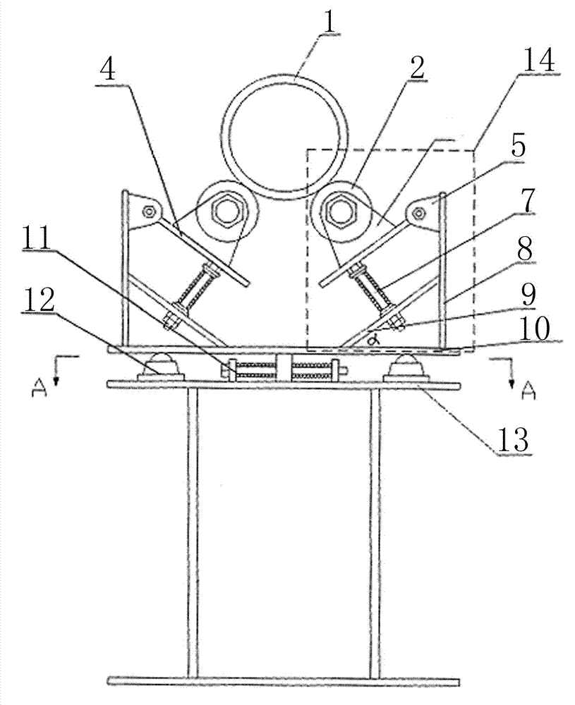
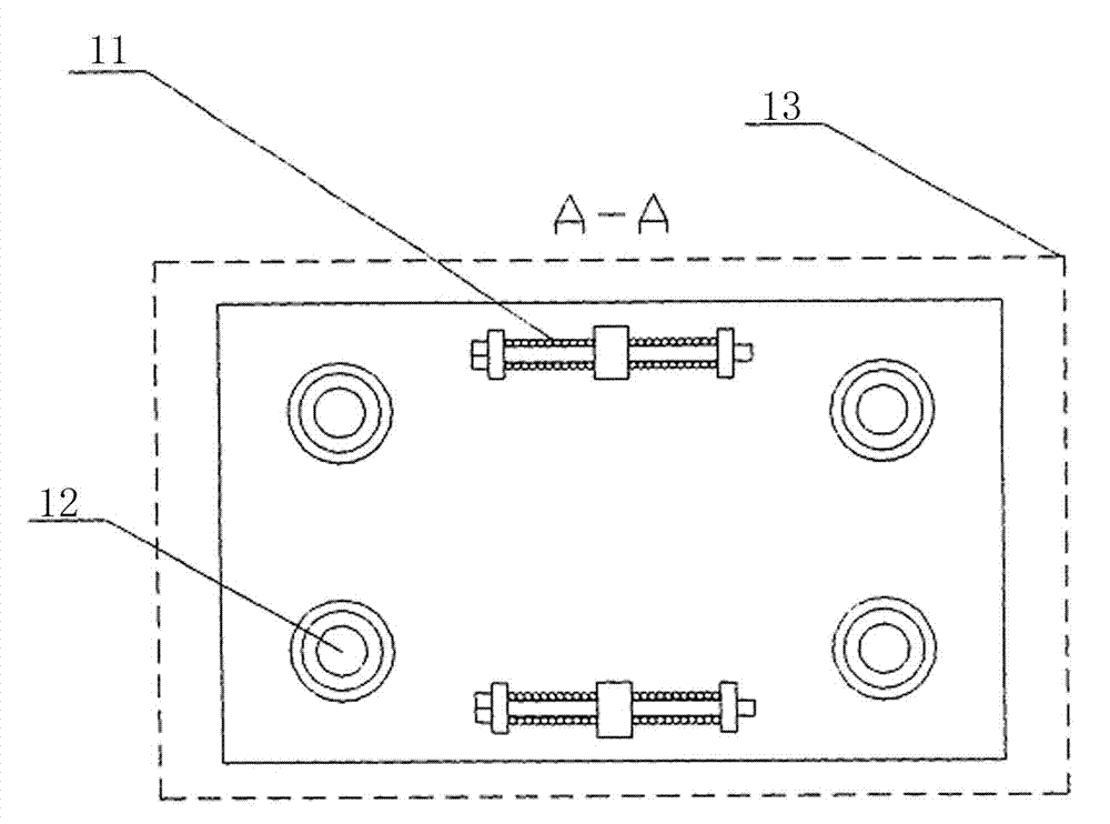
[0014] As shown in Figure 1, the laser cutting fixture includes a bracket 13, and two horizontal adjustment springs 11 and four horizontal support balls 12 symmetrically arranged between the bracket 13 and the movable support plate 10 are provided. The horizontal adjustment spring 11 is formed by connecting two springs in series through connecting rods, and the connecting rods also pass through the spring connecting seats respectively located on the bracket 13 and the movable support plate 10 . The horizontal support ball 12 is fixed on the panel of the support 13 .
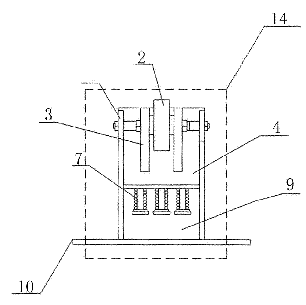
[0015] Two clamping parts 14 with left and right symmetry are arranged on the movable supporting plate, and its structure is as follows: figure 2 As shown, for the sake of clarity, the connection fixing plate 8 is deleted in the figure. The connecting fixed plate 8 is vertically positioned at one side of the movable support plate 10, and a spring guide rod fixed plate 9 is arranged between the connected fixed p...
PUM
 Abstract
Description
Claims
Application Information