Method of manufacturing PZT-based ferroelectric thin film and PZT-based ferroelectric thin film

A technology of ferroelectric thin film and manufacturing method, applied in thin film/thick film capacitors, capacitors with variable voltage, piezoelectric effect/electrostrictive or magnetostrictive motors, etc. Density and other issues to achieve the effect of preventing cracking

Inactive Publication Date: 2013-10-23
MITSUBISHI MATERIALS CORP
View PDF3 Cites 11 Cited by
  • Summary
  • Abstract
  • Description
  • Claims
  • Application Information

AI Technical Summary

Problems solved by technology

However, in the production of the relatively thick film formed by one coating, the film tends to be cracked and the film density tends to decrease.

Method used


Image

  • Method of manufacturing PZT-based ferroelectric thin film and PZT-based ferroelectric thin film
  • Method of manufacturing PZT-based ferroelectric thin film and PZT-based ferroelectric thin film
  • Method of manufacturing PZT-based ferroelectric thin film and PZT-based ferroelectric thin film

Examples


Embodiment 1

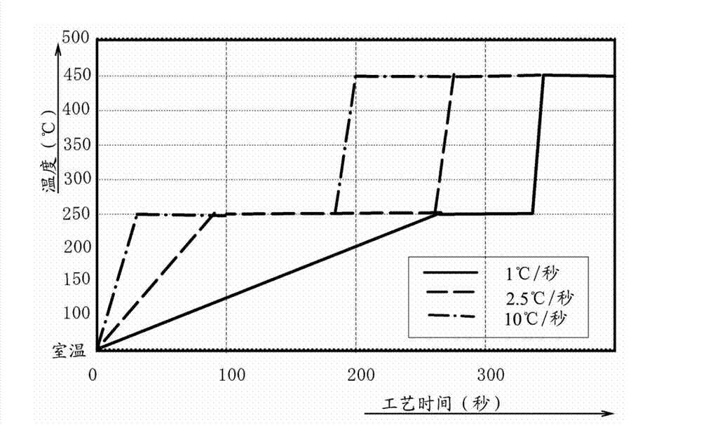
[0064] In Example 1, in the provisional sintering stage based on two-stage provisional sintering, the sol film obtained in the coating stage was provisionally sintered by infrared rays. The specific temporary sintering conditions are as follows: the temperature is raised from 25° C. to 275° C. at a rate of 1° C. / s, kept for 3 minutes, and then raised to 450° C. at a rate of 2.5° C. / s and kept for 5 minutes. Next, in the sintering stage, the amorphous film obtained in the temporary sintering is fired at a heating rate of 5° C. / second, 700° C., and a holding time of 5 minutes, thereby obtaining a PZT ferroelectric thin film.

Embodiment 2

[0066] In Example 2, in the provisional sintering stage based on two-stage provisional sintering, the sol film obtained in the coating stage was provisionally sintered by infrared rays. The specific temporary sintering conditions are as follows: the temperature is raised from 25° C. to 275° C. at a rate of 1° C. / s, kept for 3 minutes, and then raised to 450° C. at a rate of 10° C. / s and kept for 5 minutes. Next, in the sintering stage, the amorphous film obtained in the temporary sintering is fired at a heating rate of 5° C. / second, 700° C., and a holding time of 5 minutes, thereby obtaining a PZT ferroelectric thin film.

Embodiment 3

[0068] In Example 3, in the provisional sintering stage based on two-stage provisional sintering, the sol film obtained in the coating stage was provisionally sintered by infrared rays. The specific temporary sintering conditions are as follows: the temperature is raised from 25° C. to 275° C. at a rate of 1° C. / s, kept for 3 minutes, and then raised to 450° C. at a rate of 25° C. / s and kept for 5 minutes. Next, in the sintering stage, the amorphous film obtained in the temporary sintering is fired at a heating rate of 5° C. / second, 700° C., and a holding time of 5 minutes, thereby obtaining a PZT ferroelectric thin film.


PUM

PropertyMeasurementUnit
thicknessaaaaaaaaaa
refractive indexaaaaaaaaaa

Abstract

The invention provides a method of manufacturing PZT-based ferroelectric thin film and a PZT-based ferroelectric thin film. Disclosed is the method of manufacturing a PZT-based ferroelectric thin film on a lower electrode by coating, calcining, and then firing so as to crystallize a PZT-based ferroelectric thin film-forming composition on the lower electrode of a substrate having the lower electrode in which a crystal plane is oriented in a (111) axis direction. A PZT-based ferroelectric thin film-forming composition is coated on the surface of the lower electrode using a CSD method. Calcination is slowly carried out on a formed sol film in a temperature pattern including a first holding step in which the temperature of the composition is increased from a predetermined temperature such as room temperature using infrared rays and the composition is held at a temperature in a range of 200 DEG C. to 350 DEG C. and a second holding step in which the temperature of composition is increased from the holding temperature of the first holding step and is held at a temperature in a range of 350 DEG C. to 500 DEG C. higher than the holding temperature of the first holding step.

Description

technical field [0001] The present invention relates to a method of manufacturing a PZT-based ferroelectric thin film by temporarily sintering and firing after forming a relatively thick film on a substrate by chemical solution deposition (CSD, Chemical Solution Deposition). Background technique [0002] In recent years, a PZT-based ferroelectric thin film in which a relatively thick film (thick film) of 100 nm or more is formed by applying a solution containing a composition for forming a PZT-based ferroelectric thin film once on a substrate by the CSD method has been adopted. method. This is because there is a demand for a method of improving the piezoelectric characteristics of piezoelectric elements and the like using a PZT-based ferroelectric thin film as a material, and manufacturing a PZT-based ferroelectric thin film with a crystal orientation of (100) or (111) at a lower cost. However, in the production of the above-mentioned relatively thick film formed by one app...

Claims


Application Information

Patent Timeline
Patent Type & Authority Applications(China)
IPC IPC(8): C01G25/00C04B35/622C04B35/491
CPCH01B13/06H01L41/318H03H9/02574H01G7/06H01L29/784H01L45/147H01L41/1876H01L37/025G02F1/055H01L45/1608H02N2/001H01L29/78391C23C18/1283H01G4/33H01L28/55C23C18/1216H01G4/1245H01L41/09Y10T428/265H10N15/15H10N30/8554H10N30/078H01B3/10C04B35/49H01B17/62H01G4/10
Inventor 土井利浩樱井英章渡边敏昭曽山信幸
Owner MITSUBISHI MATERIALS CORP
Why Eureka
Try Eureka