Reformed Gas Production Method and Reformed Gas Production Apparatus

a gas production method and gas production apparatus technology, applied in the direction of sustainable manufacturing/processing, bulk chemical production, final product manufacturing, etc., can solve the problems of large catalyst requirements, inability to provide compact reformers, and preventing stable use of apparatuses

Inactive Publication Date: 2008-10-30
OSAKA GAS CO LTD
View PDF8 Cites 13 Cited by
  • Summary
  • Abstract
  • Description
  • Claims
  • Application Information

AI Technical Summary

Benefits of technology

[0094]That is, according to this eleventh characteristic means, simultaneously running the partial oxidation reaction and the steam reforming reaction in the reaction chamber or the second reaction chamber allows an overall compact reformed gas production apparatus to be formed while also allowing the rate of reaction to be increased in order to produce a large amount of reformed gas, such as hydrogen. In the case of a compact reformed gas production apparatus for a mobile or a stationary application, the heat that is recovered by a heat exchanger, for ex...

Problems solved by technology

However, this autothermal reformer with pre-reformer has the problem that if the pre-reformer is adopted for steam reforming, then the steam reforming reaction, whose rate of reaction is slower than that of the partial oxidation reaction, is performed at low temperatures, thus requiring large amounts of catalyst and therefore not allowing the reformer to be provided compact.
Additionally, there is also the problem that if this autothermal reformer with pre-reformer is employed in the reforming system of an automobile fuel cell or a home fuel cell, in which starting and stopping is necessary on daily basis, then, because starting...

Method used


Image

  • Reformed Gas Production Method and Reformed Gas Production Apparatus
  • Reformed Gas Production Method and Reformed Gas Production Apparatus
  • Reformed Gas Production Method and Reformed Gas Production Apparatus

Examples


working example 1

Activation of the Reforming Apparatus when the Fuel Gas is Propane

[0120]The characteristics of the rise in temperature due to the catalytic combustion of hydrogen were measured to assess the activation state. The microreactor 4A was filled with 33 mL of a ruthenium-based reforming catalyst Ru / Al2O3 (2 wt % Ru / alumina substrate, particle diameter: 0.5 to 1.0 mm). The other conditions were: propane (C3H8) supply rate 176 mL / min, hydrogen supply rate 158 mL / min, and oxygen supply rate 79 mL / min. When the mixed gas of hydrogen, oxygen, and propane was introduced at room temperature into the reactor 4 under these conditions, the catalyst-mediated hydrogen combustion reaction heated the catalyst-filled layer, raising its temperature. FIG. 4 shows the characteristics of the rise in the temperature of the catalyst-filled layer inlet at this time, and after approximately 40 minutes it had reached 400° C. (suitable operating temperature).

[0121]It should be noted that during this ope...

working example 2

Reforming Propane with a Ruthenium-Based Catalyst

[0122]The partial oxidation and steam reforming reactions of propane gas were performed using the same apparatus as that of Working Example 1. In this experiment, air was used as the oxygen-containing gas.

[0123]The experiment conditions were as follows.

catalystruthenium supported on aluminacatalyst fill amount3.3 mLfill height1.0 cmreaction gaspropane + air + steamO2 / C (mole ratio)0.3 to 1.4S / C2.5SV10000 h−1inlet temperature300° C.

[0124]FIG. 5 shows the experiment results when, at SV=10000 h−1 and a Tin of 300° C., the O2 / C ratio is altered over a range of 0.3 to 1.4 and S / C is changed to 2.5.

[0125]The results of the experiment indicate the following.

[0126]The greater the O2 / C ratio, the higher the maximum temperature Tmax within the catalyst layer, which is the reforming reaction region, and the catalyst layer outlet temperature Tout are with respect to the inlet temperature Tin. As a result, it was clear that it is possibl...

working example 3

Reforming Propane With a Nickel-Based Catalyst

[0129]Using a nickel catalyst Ni / Al2O3 (nickel concentration 22 wt %, alumina substrate) in lieu of a ruthenium-based catalyst, propane gas was subjected to partial oxidation and steam reforming using the same apparatus as that of Working Example 1. The experiment conditions and results are shown in FIG. 6. It is clear that propane gas is stably reformed into hydrogen and methane, for example.

[0130]It should be noted that after being loaded into the microreactor, the Ni catalyst was reduced for one hour at 400° C. by nitrogen gas that included 10% hydrogen.

[0131]After the reaction, the reactor was returned to room temperature, dismantled and examined, and carbon deposition was not found to have occurred inside the reactor or on the catalyst surface.


PUM


Abstract

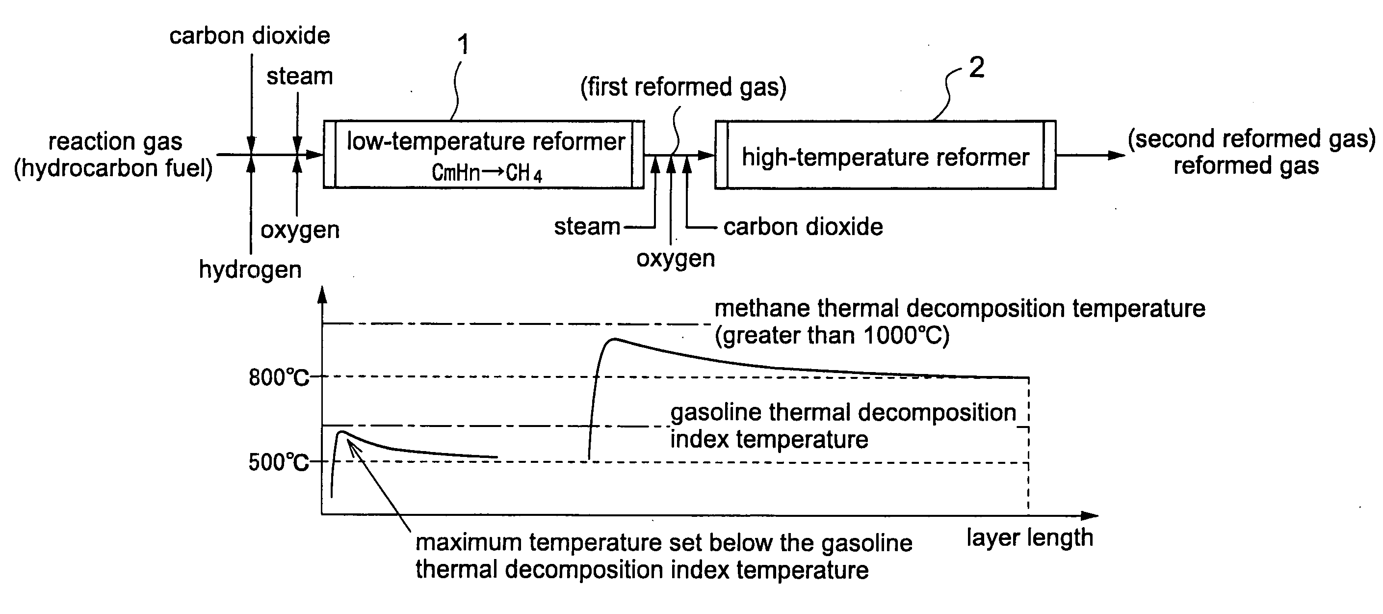
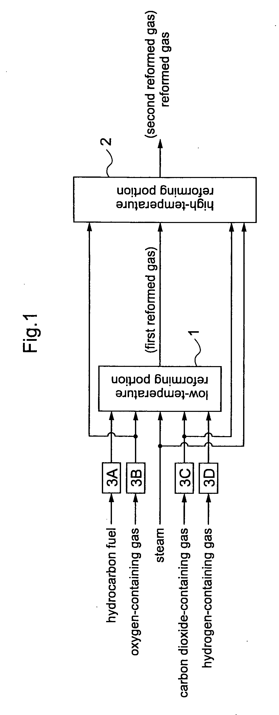
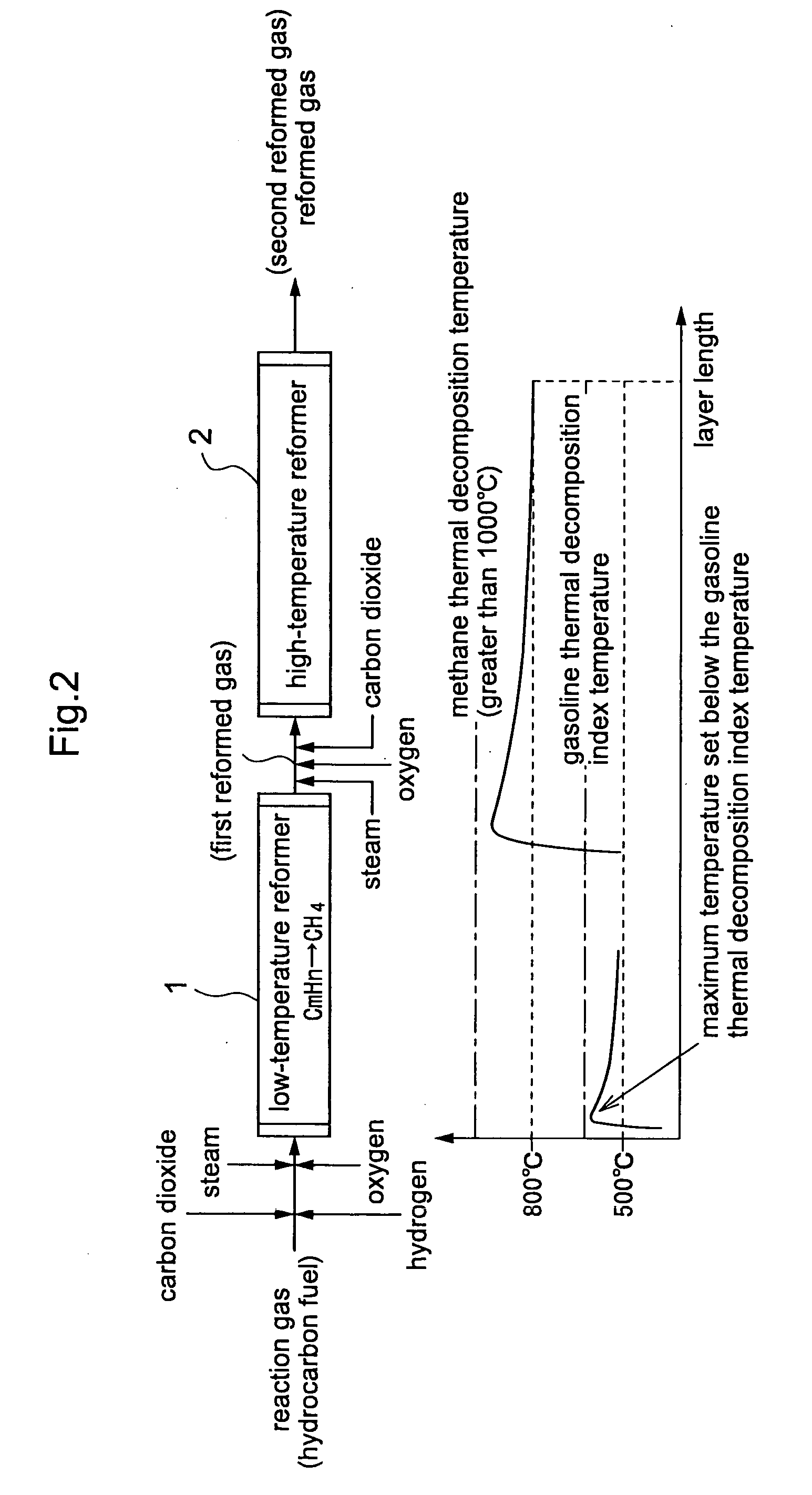
The invention provides a method for operating a reformed gas production apparatus with which it is possible to achieve a high reforming efficiency while preventing a drop in catalyst activity due to the deposition of carbon. The reformed gas production method uses a reforming catalyst to reform a fuel that contains a hydrocarbon having at least two carbon atoms to produce a reformed gas that includes methane, hydrogen, and carbon monoxide. With this method, a fluid that includes the fuel, at least one of steam and a carbon dioxide-containing gas, and an oxygen-containing gas, is supplied to a reforming reaction region, and with the thermal decomposition index temperature of the fuel, which is determined by the type and the concentration of the hydrocarbons having at least two carbon atoms that make up the fuel, serving as an upper limit temperature of the reforming reaction region, the fluid is brought into contact with the reforming catalyst to produce the reformed gas.

Description

TECHNICAL FIELD[0001]The present invention is related to reformed gas production methods and reformed gas production apparatuses for reforming hydrocarbon fuels to produce a synthesis gas that includes hydrogen and carbon monoxide.BACKGROUND ART[0002]This synthesis gas can be produced by reforming hydrocarbons or methanol, for example, and a reformed gas production apparatus that produces synthesis gas through such fuel reforming can be employed in the fields of synthesis gas production, such as the production of liquid fuel from natural gas (GTL), and the production of hydrogen for fuel cells, for example.[0003]Currently, the three methods of steam reforming, partial oxidation, and autothermal reforming, which combines these two methods, are the primary methods for reforming hydrocarbon fuels.[0004]Steam reforming is primarily used in the field of hydrogen production because of the high H2 / CO ratio in the synthesis gas that it yields through Equation 1 below, and is employed for ma...

Claims


Application Information

Patent Timeline
IPC IPC(8): B01J8/00C01B3/38C01B31/18C01B32/40
CPCB01J8/0492Y02E60/50B01J19/30B01J2208/00061B01J2208/00203B01J2208/00415B01J2208/00522B01J2208/00849B01J2208/00973B01J2208/025B01J2219/0004B01J2219/30215B01J2219/30223C01B3/382C01B2203/0244C01B2203/085C01B2203/1047C01B2203/1058C01B2203/1247C01B2203/142C01B2203/143C01B2203/1614C01B2203/1619C01B2203/169C10L3/08H01M8/0612B01J8/0496Y02P20/52Y02P70/50
Inventor OKADA, OSAMUYOKOYAMA, KOTAINOUE, NAOKI
Owner OSAKA GAS CO LTD
Why Eureka
Try Eureka