A support device for a bulb tubular unit

A technology of bulb tubular flow and support devices, which is applied in the direction of mechanical equipment, engine components, machines/engines, etc., can solve problems affecting the safe operation of bulb tubular units, and achieve the effect of preventing left and right swing and avoiding displacement

Active Publication Date: 2016-01-13
DONGFANG ELECTRIC MACHINERY
View PDF6 Cites 0 Cited by
  • Summary
  • Abstract
  • Description
  • Claims
  • Application Information

AI Technical Summary

Problems solved by technology

In this Chinese patent document, there are multiple fulcrums on the operating oil pipe in the main shaft, and the distance between each two fulcrums is relatively small, so that the operating oil pipe will not produce large deflection in the main shaft, and the stress on the operating oil pipe is not large , can ensure that the operating oil pipe will not break, but when the bulb tubular unit is running, the operating oil pipe rotates with the main shaft at high speed. Since there is no support outside the main shaft, the relative displacement of the main shaft and the operating oil pipe inside the main shaft will occur during long-term operation, thus directly Affect the safe operation of bulb tubular unit

Method used


Image

  • A support device for a bulb tubular unit
  • A support device for a bulb tubular unit
  • A support device for a bulb tubular unit

Examples


Embodiment 1

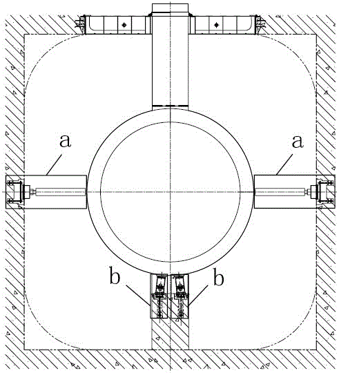
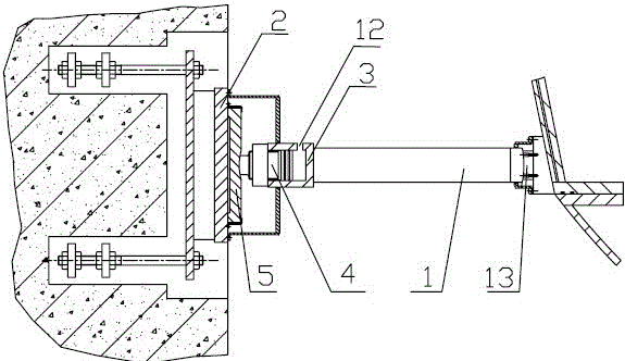
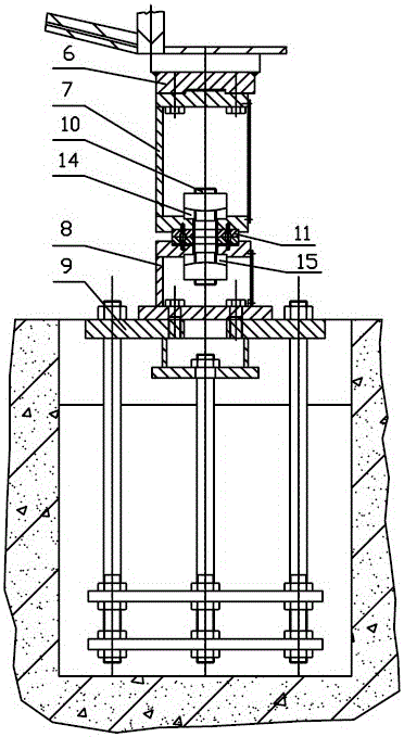
[0032] A support device for a bulb tubular unit, including a horizontal support mechanism and a vertical support mechanism, the horizontal support mechanism includes a support rod 1, a first base plate 2 connected to the foundation of the flow channel, and a piston device connected to one end of the support rod 1, the piston The device includes a piston cylinder 3 and a ball piston 4 arranged in the piston cylinder 3. The ball piston 4 is connected to the first base plate 2 through an elastic spherical support seat 5, and the other end of the support rod 1 is connected to the generator of the bulb tubular unit. There is a gap between the bulb body, the elastic spherical support seat 5 and the first base plate 2; the vertical support mechanism includes an upper support seat 6, a middle support seat 7, a lower support seat 8 and a second support seat connected to the flow channel foundation. The base plate 9, the upper support base 6 is located at the lower end of the generator b...

Embodiment 2

[0035] A support device for a bulb tubular unit, including a horizontal support mechanism and a vertical support mechanism, the horizontal support mechanism includes a support rod 1, a first base plate 2 connected to the foundation of the flow channel, and a piston device connected to one end of the support rod 1, the piston The device includes a piston cylinder 3 and a ball piston 4 arranged in the piston cylinder 3. The ball piston 4 is connected to the first base plate 2 through an elastic spherical support seat 5, and the other end of the support rod 1 is connected to the generator of the bulb tubular unit. There is a gap between the bulb body, the elastic spherical support seat 5 and the first base plate 2; the vertical support mechanism includes an upper support seat 6, a middle support seat 7, a lower support seat 8 and a second support seat connected to the flow channel foundation. The base plate 9, the upper support base 6 is located at the lower end of the generator b...

Embodiment 3

[0040] A support device for a bulb tubular unit, including a horizontal support mechanism and a vertical support mechanism, the horizontal support mechanism includes a support rod 1, a first base plate 2 connected to the foundation of the flow channel, and a piston device connected to one end of the support rod 1, the piston The device includes a piston cylinder 3 and a ball piston 4 arranged in the piston cylinder 3. The ball piston 4 is connected to the first base plate 2 through an elastic spherical support seat 5, and the other end of the support rod 1 is connected to the generator of the bulb tubular unit. There is a gap between the bulb body, the elastic spherical support seat 5 and the first base plate 2; the vertical support mechanism includes an upper support seat 6, a middle support seat 7, a lower support seat 8 and a second support seat connected to the flow channel foundation. The base plate 9, the upper support base 6 is located at the lower end of the generator b...


PUM


Abstract

The invention discloses a supporting device of a bulb turbine unit. The supporting device comprises a horizontal supporting mechanism and a vertical supporting mechanism. The horizontal supporting mechanism comprises a supporting rod, a first foundation plate connected with a runner foundation, and a piston device connected with one end of the supporting rod. The other end of the supporting rod is connected with an engine bulb of the bulb turbine unit, and a gap is reserved between an elastic ball-shaped supporting base and the first foundation plate. The vertical supporting mechanism comprises an upper supporting base, a middle supporting base, a lower supporting base and a second foundation plate connected with the runner foundation. The middle supporting base and the lower supporting base are connected through a tightening screw rod, and the tightening screw rod is sleeved with a first bulb base. The pretightening effect is achieved through elastic deformation of the elastic ball-shaped supporting base, floating force of water borne by the engine bulb is offset, and therefore the bulb turbine unit can safely operate for a long time.

Description

technical field [0001] The invention relates to a bulb tubular unit, in particular to a supporting device applied to the bulb tubular unit. Background technique [0002] The generator of the bulb tubular unit is installed in a sealed bulb body that looks exactly like an incandescent bulb. In order to prevent the generator bulb body in the flow channel from swinging left and right, it is necessary to add supports on the left and right sides of the bulb body. [0003] The support structure in the prior art adopts a rigid support, and the stiffness of the rigid support is infinite. Stiffness refers to the ability of mechanical parts and components to resist deformation. The higher the rigidity of the support, the higher the natural frequency. When the natural frequency of the support is much higher than the operating frequency of the equipment, no resonance will occur during the operation, which is called rigid support. Rigid support applied to the bulb tubular unit not only ...

Claims


Application Information

Patent Timeline
Patent Type & Authority Patents(China)
IPC IPC(8): F03B11/04
CPCY02E10/20
Inventor 徐兰坤钱昌燕向春德
Owner DONGFANG ELECTRIC MACHINERY
Why Eureka
Try Eureka