Supercharge Your Innovation With Domain-Expert AI Agents!

Annular core optical fiber sensor based on annular chamber decline

An optical fiber sensor and annular core technology, which is applied in the measurement of phase influence characteristics, etc., can solve the problem that it is difficult to put into practical use, and achieve the effects of convenient chemical or physical modification, high cost performance and high sensitivity

Inactive Publication Date: 2015-06-17
HARBIN ENG UNIV
View PDF12 Cites 0 Cited by
  • Summary
  • Abstract
  • Description
  • Claims
  • Application Information

AI Technical Summary

Problems solved by technology

However, in order to maintain the collimation characteristics of the optical path, CRD technology has high requirements on the reflectivity of the mirror and the accuracy of position adjustment, so it is difficult to put it into practical use.

Method used


Image

  • Annular core optical fiber sensor based on annular chamber decline
  • Annular core optical fiber sensor based on annular chamber decline
  • Annular core optical fiber sensor based on annular chamber decline

Examples


Embodiment 1

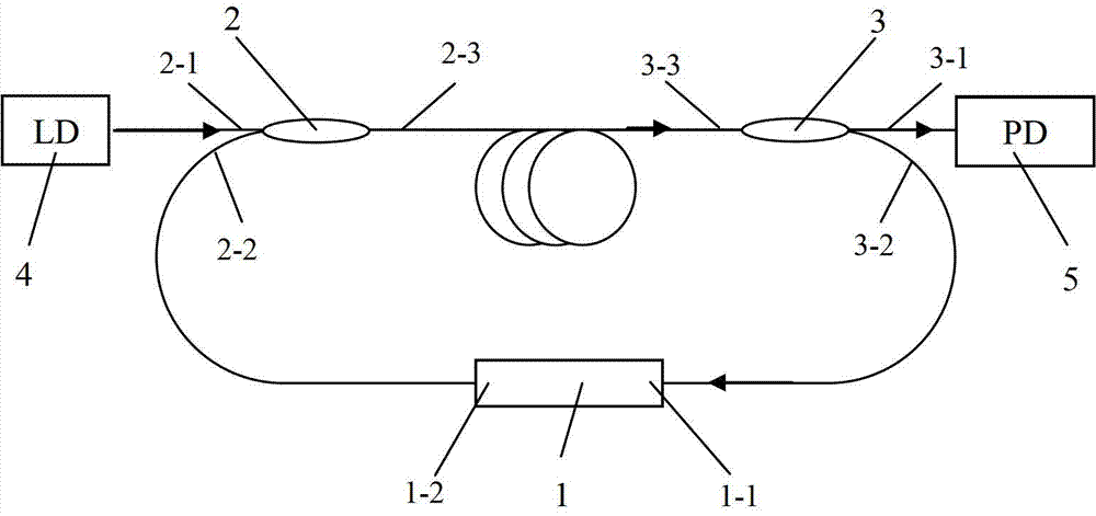
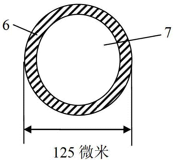
[0030] combine Figure 1-Figure 4 , a surface ring core optical fiber sensor based on optical fiber ring cavity ring down The sensing unit is a ring core 6 with a length of 3 cm and an outer diameter of 125 microns. Connected with two 1×2 fiber optic couplers 2 and 3 with a split ratio of 99.0:1.0 and one end 2-2, 3-2 with a split ratio of 99.0, two 1×2 fiber couplers have one port on one side 2 -3 and 3-3 are interconnected to form an annular cavity. The pulse light source 4 and the detector 5 are respectively connected to one end 2-1 and 3-1 of two 1×2 fiber couplers with a splitting ratio of 1.0. Wherein the ring-core fiber 1 is connected to the fiber couplers 2 and 3 by aligning the two ends 1-1 and 1-2 of the ring-core fiber 1 with the axes of the coupler fibers 3-2 and 2-2 and directly welding ( image 3 ), and then perform fusion tapering at the solder joint ( Figure 4 ), through the tapered transition zone 8 to achieve energy coupling. When the light source 4 is i...

Embodiment 2

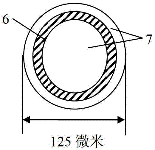
[0032] combine figure 1 , Figure 5 and Figure 6 , a ring-core optical fiber sensor sensing unit based on optical fiber ring cavity ringdown is a ring-core optical fiber 1 with a ring-core 6 outer diameter of 100 microns, and its two ends 1-1 and 1-2 are respectively connected with two splitting ratios of 99.0: 1.0 1×2 fiber coupler 2, 3 with a splitting ratio of 99.0 and one end 2-2, 3-2 connected, two 1×2 fiber couplers have 1 output port on one side 2-3 and 3- 3 are interconnected with each other to form an annular cavity. The pulse light source 4 and the detector 5 are respectively connected to one end 2-1 and 3-1 of two 1×2 fiber couplers with a splitting ratio of 1.0. The output end 1-2 of the ring-core optical fiber 1 and the optical fiber 2-2 end of the coupler 2 are directly welded through axial alignment, and then melted and tapered at the welding point, and the energy coupling is realized by using the tapered transition zone 8 ; And the incident end 1-1 of ring...

Embodiment 3

[0034] combine figure 1 and Figure 7 , a ring-core optical fiber sensor based on optical fiber ring cavity ring down, differs from embodiment 1 in that a thin metal film or dielectric film 9 is plated on the surface of the sensing part of the ring-shaped surface core to increase the sensitivity of the sensor.


PUM

PropertyMeasurementUnit
diameteraaaaaaaaaa
thicknessaaaaaaaaaa
lengthaaaaaaaaaa

Abstract

The invention provides an annular core optical fiber sensor based on annular chamber decline. Two ends of a section of optical fiber with a large-diameter annular core are respectively connected with one ends with high beam splitting ratios, of two 1*2 optical fiber couplers with high beam splitting ratios; one sides of the two 1*2 optical fiber couplers with one ports are mutually coupled, so as to form an annular chamber; a pulse light source and a detector are respectively connected with one ends with low beam splitting ratios, of the two 1*2 optical fiber couplers. As the optical fiber core of the sensing part of the annular core optical fiber is close to the external environment, and a strong evanescent field is available, the change of the environment such as an external liquid or a gas refractive index can be tested by measuring decline time. By using the sensor, unbeneficial influence caused by light source fluctuation can be reduced to the minimum, a measuring device is simple in structure, light and convenient, high in sensitivity and high in anti-interference capability, and is widely applied to aspects in sensing solution or gas concentration, temperature and the like.

Description

technical field [0001] The invention relates to an optical fiber sensor, in particular to a ring-core optical fiber sensor mainly used for sensing and measuring external environment refractive index, gas concentration and the like. Background technique [0002] Cavity Ringdown (CRD, Cavity Ringdown) spectroscopy technology is an ultra-high sensitivity detection absorption spectrum technology that emerged in the late 1980s. It is not affected by light intensity fluctuations and responds quickly. Great potential in pressure sensors and sensing systems. However, in order to maintain the collimation characteristics of the optical path, CRD technology has high requirements on the reflectivity of the mirror and the accuracy of position adjustment, so it is difficult to put it into practical use. [0003] Fiber Loop Ring Down technology (FLRD, Fiber Loop Ring Down) is the development of traditional CRD technology, which was first proposed by Stewart et al. in 2001, and was origina...

Claims


Application Information

Patent Timeline
Patent Type & Authority Patents(China)
IPC IPC(8): G01N21/41
Inventor 关春颖钟幸李树强刘志海苑立波
Owner HARBIN ENG UNIV
Features
  • R&D
  • Intellectual Property
  • Life Sciences
  • Materials
  • Tech Scout
  • Unparalleled Data Quality
  • Higher Quality Content
  • 60% Fewer Hallucinations
Learn More